- All
- Product Name
- Product Keyword
- Product Model
- Product Summary
- Product Description
- Multi Field Search
Please Choose Your Language

Views: 0 Author: Site Editor Publish Time: 2026-08-15 Origin: Site


The reliability of a backup power system hinges entirely on the accuracy of its physical implementation. A single undersized conductor or misconfigured control wire in a 3-phase system can lead to catastrophic thermal failure or total loss of critical loads. Facility managers and electrical contractors face the challenge of translating a theoretical schematic into a compliant, safe, and scalable physical installation. This requires balancing precise cable sizing, fault current ratings, and the integration of modern distributed energy resources without violating local electrical codes. This guide deconstructs the technical requirements of 3-phase ATS installations, providing an evidence-based framework for calculating cable specifications, evaluating component integrations, managing dual-mode changeovers, and mitigating common commissioning risks.
Cable Sizing is Non-Negotiable: Accurate conductor sizing must account for continuous load, voltage drop over distance, and short-circuit withstand ratings, not just baseline ampacity.
Control Wiring Dictates Reliability: Standard installations typically require a precise 7-wire control configuration and a properly seated wiring harness between the ATS and the generator to ensure fail-safe communication and phase synchronization.
Dual-Mode Functionality Adds Resilience: Incorporating manual override capabilities into the ATS panel wiring ensures operational continuity during automated controller failures.
Modern Integration Requires Specific Isolators: Incorporating solar or smart grids necessitates dedicated components like a Manual PV Isolator Switch and intelligent breakers to safely manage bidirectional power flow.
Thermal Management Prevents Failure: Utilizing proper insulating bushings, thermal sensors, and strict torque specifications during termination is critical to preventing high-resistance faults.
Defining the baseline requirements for a compliant transfer switch installation is the first step in any commercial or industrial power project. You must ensure a seamless transition between normal utility power, alternative power from a generator or inverter, and the critical load panel. A well-executed 3 phase ATS wiring diagram serves as the exact blueprint for this physical integration. It maps out the heavy-duty power flow, the low-voltage control logic, and the mechanical safety interlocks required to prevent catastrophic electrical faults.
Mapping the primary connections requires strict attention to phase alignment and system grounding. You must terminate the utility input to the designated L1, L2, L3, and Neutral lugs. You repeat this exact sequence for the generator input and the load output. Crossing any of these phases creates immediate equipment hazards, particularly for three-phase motors that will run backward if the phase rotation is reversed.
Neutral switching demands careful evaluation based on your specific grounding scheme. You must decide between a 3-pole and a 4-pole transfer switch before pulling any wire. A 4-pole switch physically disconnects the neutral conductor during the transfer process. You need a 4-pole configuration when the generator acts as a separately derived system with its own neutral-to-ground bond. This prevents nuisance tripping of upstream ground-fault protection relays. If the generator shares a solid neutral connection with the utility service, a standard 3-pole switch suffices.
The mechanical changeover mechanism relies on a strict break-before-make operation. The switch must physically disconnect the load from the utility before it connects to the generator. This physical interlock prevents the cross-connection of out-of-phase power sources. Cross-connecting live sources causes massive arc flashes, immediate equipment destruction, and severe safety hazards for personnel.
Executing the wiring harness connection dictates the responsiveness of the entire system. Most commercial generator-to-ATS communications require a standard 7-control-wire configuration. You must route these low-voltage wires in a separate conduit away from the high-voltage power cables. Physical separation prevents electromagnetic interference from disrupting the sensitive control signals.
The standard 7-wire control harness typically breaks down into the following functional groups:
Utility Phase A Voltage Sensing
Utility Phase B Voltage Sensing
Utility Phase C Voltage Sensing
Generator Start Signal (Normally Open Contact)
Generator Start Signal (Common Contact)
Switch Position Indicator - Normal/Utility
Switch Position Indicator - Emergency/Generator
Voltage sensing lines continuously monitor the utility feed. The ATS controller looks for phase loss, under-voltage, or over-voltage conditions across all three phases. When the voltage drops below a programmed threshold, the controller initiates the transfer sequence. It closes the two-wire start contact, waits for the generator to reach proper voltage and frequency, and then triggers the mechanical transfer mechanism.
Integrating manual transfer capabilities adds essential resilience to your power system. Automated digital controllers can fail due to lightning strikes, power surges, or internal component degradation. Dual-mode functionality allows operators to bypass the digital logic entirely and operate the switch manually.
You execute manual overrides using a physical handle or mechanical push buttons located directly on the transfer mechanism inside the enclosure. The wiring diagram must account for safety interlocks during manual operation. The system must physically block manual transfer if the target power source is dead or out of phase. This protects operators from accidentally closing the switch into a dead bus under a heavy load, which can cause severe arcing.
Accurate cable sizing forms the physical foundation of any transfer switch installation. You cannot rely solely on baseline ampacity charts found in basic electrical guides. You must calculate continuous load demands, account for voltage drop over long conduit runs, and evaluate fault current limits. Undersized cables overheat, degrade their insulation over time, and eventually cause electrical fires.
Determining the maximum continuous load requires a systematic methodology. You must inventory all connected equipment on the backup circuit, including HVAC units, servers, and lighting panels. Electrical codes typically require applying a 125% safety margin for continuous loads. If your critical load draws 100 amps continuously, you must size the conductors and the breaker for at least 125 amps.
Evaluating the Short Circuit Current Rating (SCCR) is equally critical. The SCCR defines the maximum fault current the switch and its connected cables can withstand without sustaining catastrophic damage. The cables must survive this massive energy surge until the upstream overcurrent protection device clears the fault. If the available fault current from the utility exceeds the cable's withstand rating, the conductors will literally vaporize inside the conduit. You must coordinate the cable size, the ATS SCCR rating, and the upstream breaker clearing time to ensure a safe installation.
Long cable runs introduce electrical resistance, causing a voltage drop at the load end. Excessive voltage drop damages sensitive electronics, causes motors to overheat, and reduces the efficiency of lighting systems. You should maintain a voltage drop below 3% for critical power circuits and below 5% for overall feeder circuits.
You calculate 3-phase voltage drop using a specific formula: Vd = (1.732 * I * L * R) / 1000. In this formula, 'I' represents the load current in amps, 'L' is the one-way circuit length in feet or meters, and 'R' is the conductor resistance per 1000 units. You must increase the wire gauge if the calculation exceeds the 3% threshold, regardless of the baseline ampacity rating.
Choosing between copper and aluminum conductors involves distinct trade-offs in the field. Copper offers superior conductivity and requires a smaller conduit footprint. It bends easily in tight enclosures and resists oxidation. Aluminum costs significantly less and weighs less, making long pulls easier. However, aluminum requires larger wire gauges to match copper's ampacity. You must also apply a specialized anti-oxidant compound to all aluminum terminations to prevent high-resistance connections.
| Conductor Material | Conductivity Profile | Termination Requirements | Cost & Weight Factor |
|---|---|---|---|
| Copper (Cu) | High conductivity, lower resistance per foot. Allows for smaller conduit sizes. | Standard mechanical lugs, no anti-oxidant paste required. Easier to torque. | Higher upfront cost, heavier weight per foot. Harder to pull over long distances. |
| Aluminum (Al) | Lower conductivity, requires larger gauge to match copper ampacity. | Requires anti-oxidant paste (e.g., Noalox) and specific torque checks. | Lower cost, significantly lighter weight. Prone to thermal expansion loosening. |
Practical application requires matching the wire gauge to specific switch ratings and environmental conditions. When installing a standard 63A Automatic Transfer Switch, you must select the appropriate conductor based on the 125% rule. For a 63A continuous load, the calculation requires a wire rated for at least 78.75A. Using copper wire rated at 75°C, you typically need a 4 AWG (21mm²) conductor. This assumes a standard ambient temperature of 30°C and a short cable run.
You must apply derating factors based on environmental conditions. High ambient temperatures reduce a cable's ability to dissipate heat. If you route the cables through a hot mechanical room or across a sun-exposed roof, you must increase the wire size. Conduit fill limits also require derating. Grouping more than three current-carrying conductors in a single conduit reduces their effective ampacity due to trapped heat. You must consult local electrical code tables to apply the correct derating multipliers before finalizing your cable schedule.
Modern energy architectures expand far beyond traditional utility and diesel generator setups. Facilities increasingly incorporate solar arrays, battery energy storage systems (BESS), and IoT-enabled load management panels. You must adapt the physical ATS installation to accommodate these bidirectional power flows safely and efficiently.
Integrating solar power into a backup system requires strict isolation protocols. You cannot simply wire a solar inverter directly into the ATS alternate input. Grid-tied inverters must shut down during a utility outage to prevent backfeeding the grid. Backfeeding poses a lethal threat to utility line workers attempting to repair the downed lines.
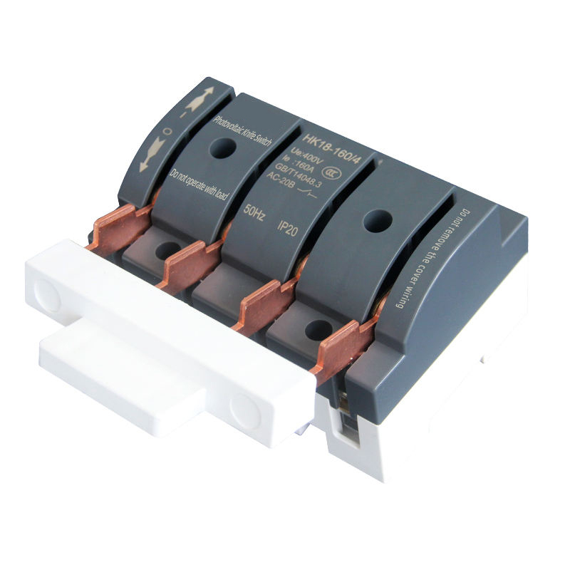
You must install a Manual PV Isolator Switch within the ATS ecosystem. Position this isolator between the solar inverter output and the ATS alternate power input or the main distribution panel. This switch provides a physical, lockable disconnect point. It ensures safe maintenance of the transfer switch without exposure to live solar DC or AC voltage.
Wiring considerations differ significantly between DC-coupled and AC-coupled solar backup systems. AC-coupled systems require careful frequency shifting configuration. The backup generator or battery inverter must alter the microgrid frequency to curtail solar production when the batteries reach full charge or the load drops. Your wiring diagram must route the AC-coupled solar feed downstream of the ATS to allow this frequency control to function properly.
Intelligent power management enhances the efficiency of limited backup power sources. Deploying a Smart WiFi Circuit Breaker downstream of the ATS enables granular control over specific branch circuits. You can program these devices to automatically shed non-critical loads, such as decorative lighting or secondary HVAC units, during generator operation. This prevents generator stalling and optimizes fuel consumption during extended outages.
You must evaluate the cybersecurity and latency risks of cloud-connected breakers. Relying on external cloud servers for critical power management introduces vulnerability. Internet outages often accompany power outages. You should configure smart breakers to default to a safe, pre-programmed state if they lose network connectivity. Isolate these devices on a dedicated, secure VLAN to prevent unauthorized access to your power infrastructure.
Aligning the physical switch mechanism with your facility requirements ensures long-term reliability. You must evaluate the internal architecture of the ATS, plan for future scalability, and adhere to strict safety standards. Component selection directly impacts maintenance schedules, overall system footprint, and lifecycle performance.
You must choose between contactor-based and circuit breaker-based transfer switches. Contactor-based switches use heavy-duty magnetic contactors to move the load between sources. They offer a compact footprint, extremely fast transfer speeds, and high endurance for frequent switching applications. However, they do not provide integrated overcurrent protection. You must install separate circuit breakers upstream to protect the switch and the conductors.
Circuit breaker-based switches utilize molded case circuit breakers equipped with motor operators. These units combine the transfer mechanism and overcurrent protection into a single enclosure. This reduces the overall wall space required and simplifies the wiring diagram. They generally cost more upfront and have slightly slower transfer times compared to contactors. You must weigh these trade-offs based on your available space, budget, and fault current requirements.
Designing the enclosure and conduit layout requires anticipating future facility growth. You should never size conduits exactly to the current load requirement. Always design the conduit layout to accommodate at least 20% to 30% future load expansion. This prevents costly tear-outs and repulls when upgrading equipment later.
Future-proofing also involves planning for Uninterruptible Power Supply (UPS) integration. If your facility adds sensitive data servers or medical imaging equipment, you will need a UPS downstream of the ATS. The ATS wiring must account for the UPS bypass circuits and maintenance isolation breakers. Leave adequate physical space on the electrical backboard for these future additions and size the neutral conductor to handle potential harmonic currents generated by the UPS.
Adhering to electrical standards ensures legal compliance and physical safety. In North America, you must follow NEC Article 700 for emergency systems, Article 701 for legally required standby systems, or Article 702 for optional standby systems. International installations must comply with IEC 60947-6-1 standards for transfer equipment. These codes dictate enclosure NEMA ratings, clearance spaces, and specific labeling requirements.
Thermal management prevents high-resistance faults at termination points. You must specify insulating bushings where cables enter the metal enclosure. Bushings protect the cable jacket from abrasion caused by generator vibration. Integrating thermal sensors at the main lug termination points adds a critical layer of safety. These sensors detect abnormal temperature rises caused by loose connections. They trigger an alarm before the connection arcs and causes an enclosure fire.
Physical installation introduces variables that a schematic cannot fully capture. Human error, environmental factors, and mechanical stresses threaten system integrity. You must implement rigorous testing and mitigation strategies to address these realities before energizing the system.
Phase reversal stands as one of the most destructive wiring errors in a 3-phase system. You must maintain consistent phase rotation across both the utility and generator inputs. If you accidentally wire the generator input as L2-L1-L3 instead of L1-L2-L3, the phase rotation reverses. When the ATS transfers power, three-phase motors will instantly spin backward. This destroys HVAC compressors, elevator drives, and industrial pumps within seconds.
You mitigate this risk by utilizing a phase rotation meter prior to final commissioning. You must measure the rotation on the utility feed and verify it matches the generator feed exactly. Strict color-coding of all conductors during the wire pull prevents confusion at the termination lugs. Use brown, orange, and yellow tape for 480V systems, or black, red, and blue for 208V systems.
Improperly seated control harnesses compromise the entire changeover logic. If the utility sensing wires vibrate loose, the controller assumes a power failure and starts the generator unnecessarily. You must secure all harness plugs with locking clips, use zip ties to manage slack, and route them away from high-vibration areas inside the enclosure.
Termination failures result directly from incorrect torque application. Over-torquing the mechanical lugs strips the threads and damages the fine conductor strands. Under-torquing leaves microscopic air gaps that cause electrical arcing and rapid heat buildup. You must use a calibrated torque wrench for every single power connection. Mark each lug with torque paint after tightening to provide visual verification during future maintenance inspections.
Developing a rigorous pre-energization checklist prevents catastrophic startup failures. You must perform Megger testing on all power cables before connecting them to the ATS lugs.
Disconnect all cables from the utility, generator, and load panels.
Apply 500V or 1000V DC to the conductors using a Megohmmeter.
Measure the resistance between each phase, and between each phase and ground.
Verify readings are in the high megohm or gigohm range.
This detects microscopic cuts in the cable jacket caused during the wire pull. Commissioning requires simulating a complete utility failure. You must test the system in both automatic and manual modes under a partial load. Verify the generator start delay, the transfer time, and the cool-down timer. Establish a routine maintenance schedule immediately after commissioning. You should exercise the switch under load monthly and inspect all control wire harnesses for signs of thermal degradation.
Consult a licensed electrical engineer to validate your continuous load calculations and fault current withstand requirements before pulling any wire.
Procure components exclusively from certified manufacturers that provide documented SCCR testing data to ensure code compliance.
Implement a strict torque-wrench-only policy for all power terminations and mark each lug with torque paint to eliminate high-resistance connections.
Install physical isolation switches for all integrated renewable energy sources to protect maintenance personnel from backfed voltage.
Execute a comprehensive Megger testing protocol on all conductors prior to final system energization to verify insulation integrity.
A: Most commercial installations use a 7-wire control harness. Three wires handle utility voltage sensing across all phases. Two wires manage the start/stop signal sent to the generator controller. The final two wires communicate the mechanical switch position status back to the main control board.
A: You must size the cables for 125% of the continuous load. For a 63A load, calculate for roughly 79A. Using 75°C rated copper wire, you typically select 4 AWG or 21mm² conductors. You must then apply derating factors for ambient temperature and conduit fill limits.
A: A dual-mode ATS includes a physical manual override mechanism, such as a heavy-duty handle or mechanical push buttons. This allows operators to safely execute the changeover process manually if the automatic digital controller fails due to lightning or component degradation.
A: You must install the PV isolator switch directly between the solar inverter output and the alternative power input of the ATS. This placement ensures safe physical isolation for maintenance and absolutely prevents the solar system from backfeeding into a dead utility grid.
A: No. While smart breakers offer excellent load management and remote monitoring, they lack mechanical interlocking. Electrical codes require a physical break-before-make mechanism for primary power transfer to prevent the lethal cross-connection of out-of-phase power sources.
A: Phase reversal occurs when any two phase wires are crossed during termination. You prevent this by strictly color-coding all cables during the pull and verifying the rotation with a phase rotation meter on both the utility and generator feeds before energizing.
A: You use the formula Vd = (1.732 * I * L * R) / 1000. 'I' is current, 'L' is distance, and 'R' is conductor resistance. You must ensure the final voltage drop remains below 3% to protect sensitive critical loads from under-voltage damage during operation.
