- All
- Product Name
- Product Keyword
- Product Model
- Product Summary
- Product Description
- Multi Field Search
Please Choose Your Language

Views: 0 Author: Site Editor Publish Time: 2026-08-10 Origin: Site


Power transfer systems carry immense operational and safety stakes. Improper wiring leads to catastrophic phase collisions. Equipment destruction and lethal backfeeding into the utility grid are real threats that facility managers face when changeover mechanisms fail. Facilities and industrial setups require seamless, fail-safe transitions between primary utility power from the local transformer and backup generators. This demands precise synchronization, load management, and fault protection across all electrical phases.
A rigorously designed 3 phase ATS wiring diagram maps out power circuits, control logic, and safety interlocks. It serves as the foundational blueprint for reliable automatic and manual changeover. By isolating high-voltage power routing from low-voltage control sequences, engineers build systems that automatically detect utility failures, safely start standby generators, and transfer critical loads without human intervention, all while maintaining strict isolation between competing power sources.
Interlock Redundancy is Non-Negotiable: A compliant ATS must utilize both mechanical and electrical interlocks to physically prevent simultaneous connection to normal power and alternative power.
Component Sizing Dictates Reliability: Selecting the correct contactors, relays, and protection devices (like an AC Miniature Circuit Breaker) based on continuous and peak load calculations prevents premature failure.
Neutral Switching Matters: Deciding between 3-pole (solid neutral) and 4-pole (switched neutral) configurations depends heavily on local grounding codes and generator alternator design.
Voltage Compatibility: Properly mapping out 120V/240V single-phase critical loads within a broader 208V/400V/480V three-phase system is essential for comprehensive facility backup.
Hybrid Scalability: Modern ATS designs must increasingly account for multi-source inputs, such as integrating solar inverters alongside traditional diesel generators.
Electricians and panel builders frequently run into trouble when they fail to separate the high-voltage power circuit from the low-voltage control logic during installation. Mixing these two distinct operational layers inside the enclosure leads to dangerous wiring errors, induced voltage on communication lines, and catastrophic short circuits. A professional schematic clearly delineates the heavy current paths from the sensitive sensing and switching logic. You have to understand this physical and electrical separation before pulling a single wire.
The power circuit handles the primary load current for the entire facility. You must map standard connections for L1, L2, L3, and Neutral perfectly from both the Normal Power source and the Alternative Power source. The utility transformer provides the primary feed, terminating at the normal side lugs. The standby generator provides the secondary feed, terminating at the emergency side lugs. Heavy-duty contactors or motorized changeover switches bridge these sources to the common load bus.
These components operate at standard three-phase voltages, typically 208V, 400V, or 480V depending on your regional grid. The power circuit wiring requires large gauge cables, often 500 MCM or larger, capable of handling maximum facility amperage. You must follow exact torque specifications on the terminal lugs. If you under-torque a lug, thermal expansion and contraction under heavy load will loosen the connection, causing arcing and eventually a panel fire. Phase rotation must match exactly between the utility and the generator. If you swap L1 and L2 on the generator side, three-phase motors will run backwards upon transfer. This causes immediate mechanical damage to pumps, fans, and industrial compressors.
| Voltage System | Phase 1 (L1) Color | Phase 2 (L2) Color | Phase 3 (L3) Color | Neutral Color |
|---|---|---|---|---|
| 208Y/120V (US Standard) | Black | Red | Blue | White |
| 480Y/277V (US Industrial) | Brown | Orange | Yellow | Gray |
| 400Y/230V (IEC Standard) | Brown | Black | Gray | Blue |
The automatic control relies on a precise step-by-step wiring sequence to transfer power when utility parameters fall out of tolerance. Phase failure relays continuously monitor the utility feed for phase loss, asymmetry, or phase reversal. Under/over-voltage monitors detect dangerous sags or surges, typically set to trigger if voltage drops below 85% or spikes above 110% of nominal. When a fault occurs, the control logic initiates a strict sequence of operations.
Utility Failure Detection: The voltage monitor detects a drop and starts the Time Delay Engine Start (TDES) timer.
Engine Start Signal: If the outage outlasts the TDES (usually 3 to 5 seconds to ignore transient dips), a dry contact closes, sending a start signal to the generator controller.
Generator Stabilization: The generator cranks and reaches rated voltage and frequency (e.g., 480V at 60Hz).
Transfer Execution: The Time Delay Normal to Emergency (TDNE) timer expires, the utility contactor opens, and the generator contactor closes, feeding the load.
Utility Restoration: Utility power returns and remains stable for the duration of the Time Delay Emergency to Normal (TDEN) timer (often 5 to 15 minutes).
Retransfer: The generator contactor opens, the utility contactor closes, and the load is back on grid power.
Engine Cooldown: The generator runs unloaded for the Time Delay Engine Cooldown (TDEC) period before shutting down.
Control circuits step down high voltage to 120V AC or 24V DC to operate relays, timers, and indicator lights. You must place an AC Miniature Circuit Breaker within the ATS panel to protect this sensitive control circuitry. Short circuits or overloads within the control wiring can destroy the entire logic board, rendering the automatic transfer function useless.
The breaker isolates the control transformer from the main power bus. Proper coordination between the ATS internal breakers and upstream distribution panels is mandatory. You should select a control breaker with a trip curve that responds instantly to internal faults while allowing normal inrush currents from contactor coils. Curve C or Curve D breakers are typical here. This local protection keeps the main power bus active and safe even if the ATS automatic control board experiences a catastrophic failure, allowing you to operate the switch manually.
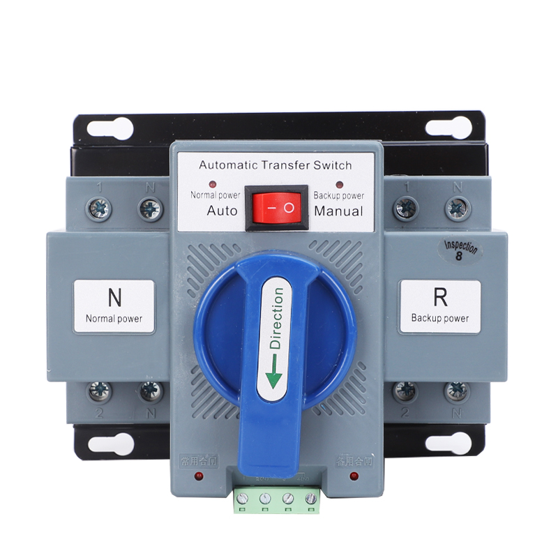
Ensuring proper grounding and avoiding nuisance tripping of Ground Fault Protection (GFP) systems dictates your switching configuration. The choice between three and four poles impacts the entire facility grounding scheme and determines whether the system complies with local electrical codes like NEC Article 700.
| Feature | 3-Pole ATS Configuration | 4-Pole ATS Configuration |
|---|---|---|
| Neutral Connection | Solid, unswitched neutral shared across sources. | Switched neutral, completely isolated during transfer. |
| Generator Type | Not a separately derived system. | Separately derived system. |
| Grounding Bond | Relies on the main utility service entrance bond. | Generator has its own dedicated neutral-to-ground bond. |
| Ground Fault Protection | Prone to false trips if upstream GFP is present. | Prevents parallel neutral paths, ensuring GFP stability. |
| Application Scale | Small commercial, residential, simple setups. | Large industrial, hospitals, complex grounding grids. |
In a 3-pole configuration, the neutral remains solidly connected between the utility, generator, and load. It is unswitched and continuous. You use this setup when the generator is not a separately derived system. The generator neutral is not bonded to the ground at the generator frame. Instead, it relies entirely on the main utility service entrance for its neutral-to-ground bond.
Solid neutral configurations are common in smaller commercial setups and light industrial buildings. They simplify wiring, require less physical space in the enclosure, and reduce component costs. However, if the main utility breaker utilizes ground fault protection, a solid neutral can cause parallel paths for return current. During a power transfer, unbalanced neutral currents might travel across the ground wire. The GFP sensor reads this imbalance as a fault, leading to false trips and leaving the facility in the dark.
Switching the neutral requires a 4-pole ATS. This is mandatory when the generator acts as a separately derived system with its own dedicated neutral-to-ground bond. The 4-pole connections on the diagram ensure the utility neutral is completely severed before the generator neutral engages. This physical break prevents parallel neutral paths.
Using a 4-pole switch ensures compliance with NEC and IEC standards for ground fault isolation in complex systems. Large industrial facilities, data centers, and hospitals with multiple generators almost exclusively use 4-pole configurations. The fourth pole must be rated for the exact same amperage as the phase poles. Modern non-linear loads like LED lighting, variable frequency drives (VFDs), and server power supplies generate severe harmonic distortion, which stacks on the neutral wire. An undersized neutral pole will overheat and fail.
Matching the ATS design to specific power generation sources and load requirements ensures operational stability. Facilities no longer rely solely on diesel generators. Modern power architectures demand flexible transfer switches capable of managing diverse energy inputs and highly specific load profiles.
Backup power plans increasingly integrate renewable sources. Wiring logic must account for solar inverters and battery storage alongside traditional diesel generators. Incorporating a 63A Solar Automatic Transfer Switch requires specific prioritization logic mapped directly onto the control schematic. The diagram must show the solar and battery inverter as the primary backup source.
When the utility fails, the ATS transfers the load to the solar inverter. If battery levels drop below a critical threshold or the load exceeds inverter capacity, a secondary control circuit sends a start signal to the diesel generator. The ATS then executes a secondary transfer, moving the load from the depleted solar system to the active generator. This hybrid approach reduces fuel consumption, lowers emissions, and extends the runtime of the backup system during prolonged grid outages. You have to wire the auxiliary contacts on the solar ATS to communicate directly with the generator's start panel to make this sequence work.
Full three-phase transfer supports heavy machinery, elevators, and large HVAC systems. However, facilities often require dedicated single-phase backup for specific critical loads that cannot tolerate even momentary voltage drops. A 2P Generator Automatic Transfer Switch is often wired downstream of the main 3-phase panel to isolate and protect specific 120V/240V circuits.
Server rooms, emergency lighting arrays, and fire alarm panels operate on single-phase power. By utilizing a dedicated 2P ATS, facility managers can back up these critical circuits with a smaller, highly efficient single-phase uninterruptible power supply (UPS) or dedicated inverter. The diagram must clearly delineate the phase tapping. You pull L1 and L2 from the 3-phase bus to feed the 2P ATS, while carefully balancing the remaining facility loads across L3 to prevent phase asymmetry. If you overload L1 and L2, the resulting voltage imbalance will damage three-phase motors connected to the main bus.
Balancing the convenience of automation with the necessity of manual overrides dictates system resilience. Control boards fail. Lightning strikes destroy microprocessors. Extreme temperature fluctuations degrade relay coils. Manual operation ensures power restoration during catastrophic control failures, allowing operators to physically force a changeover when the digital brain dies.
Wiring modifications must include a manual selector switch on the enclosure door. The Auto/Off/Manual switch allows operators to bypass the digital controller safely. The diagram must show this switch routing control power directly to the contactor coils via heavy-duty manual pushbuttons. Safety protocols cannot be bypassed during manual operation; the interlocks must remain active.
The step-by-step manual changeover procedure requires strict adherence to safety protocols. First, the operator isolates the utility feed by opening the main breaker. The operator turns the selector to manual, verifies generator voltage and frequency on the panel meter, and physically engages the generator contactor using the manual handle or pushbutton. The diagram supports safe execution by visually mapping the isolation points and providing a clear sequence of operations printed directly on the panel interior.
Electrical interlocking uses normally closed (NC) auxiliary contacts to prevent phase collisions. The wiring from the generator contactor coil must pass directly through the NC contact of the utility contactor. If the utility contactor is energized, the NC contact opens. This physically breaks the circuit to the generator coil. The generator contactor cannot close, regardless of what the control board commands.
Electrical interlocks must always be backed by a physical mechanical interlock mechanism. A mechanical walking beam, sliding bar, or cam physically blocks one contactor from closing if the other is closed. This guarantees isolation even if a contactor welds shut due to a massive short circuit. Without a mechanical interlock, a welded utility contactor combined with a forced generator start will result in a dead short across the phases, destroying the panel and potentially causing an arc flash explosion.
Addressing the most common points of failure in ATS design, installation, and commissioning prevents downtime and protects personnel. A flawless diagram is useless if field execution ignores mechanical stresses, environmental factors, and strict testing protocols.
Backfeeding into the utility grid endangers utility linemen repairing downed wires. Proper ATS wiring eliminates this risk through strict mechanical interlocking and fail-safe coil wiring. Phase sequence relays are equally critical for three-phase systems. They ensure the generator's phase rotation matches the utility's rotation perfectly.
If a temporary mobile generator is connected with reversed phases, the phase sequence relay detects the mismatch instantly. It opens the control circuit and prevents the ATS from transferring to the generator. This prevents catastrophic motor damage. Running a large industrial chiller or conveyor belt backwards for even a few seconds will destroy the mechanical linkages and burn out the motor windings. You wire the phase sequence relay directly in series with the generator contactor coil to ensure it has ultimate veto power over the transfer.
Calculating the necessary amperage rating of the ATS requires analyzing highly inductive loads. HVAC compressors, heavy machinery, and large transformers draw massive inrush currents upon startup. An ATS rated for 400A continuous load might experience 2400A of inrush current for a few AC cycles.
Utilization Categories: Contactors must be sized for AC-3 or AC-33A utilization categories to handle highly inductive loads without welding the contacts.
Cable Sizing: Busbars and heavy-gauge cables must be sized for 125% of the continuous load to handle thermal buildup.
Lug Capacity: Ensure the terminal lugs can accept parallel cable runs if the amperage exceeds the capacity of a single large-gauge wire.
Short Circuit Current Rating (SCCR): The ATS must have an SCCR equal to or greater than the maximum available fault current at the installation point.
Environmental and mechanical considerations dictate the lifespan of the transfer switch. Selecting the proper NEMA or IP enclosure rating protects the internal components from dust, moisture, and corrosive gases. A NEMA 1 enclosure is strictly for clean indoor use, while NEMA 3R or 4X is required for outdoor or washdown environments.
Adhering to strict terminal torque specifications prevents arcing over time. Loose connections generate heat, leading to thermal runaway, melted insulation, and panel fires. Installers must use calibrated torque wrenches. When torquing aluminum cables into the main lugs, you have to account for cold flow of the conductors. Re-torque them after 24 hours. Infrared thermography should be used during commissioning and annual maintenance to verify all connections remain secure under full load conditions.
Standard testing procedures validate the wiring diagram against real-world conditions. Cold testing involves continuity checks and insulation resistance testing using a megohmmeter. You apply 1000V DC for one minute across the phases and to ground. This ensures no short circuits exist between phases or to ground before applying utility power. You want to see readings well above 100 megohms.
Hot testing involves a simulated utility failure. The main utility breaker is opened manually. The ATS must sense the loss, start the generator, and transfer the load within the specified time frame. A load bank test is then conducted. This verifies the generator and ATS can handle the full rated capacity for several hours without overheating, voltage drop, or control board failure. You monitor the contactor temperatures with an infrared gun during this test to ensure the contacts are seating properly.
Verify your generator's alternator grounding configuration to determine if you need a 3-pole or 4-pole transfer switch before purchasing equipment.
Calculate the maximum inrush current of your facility's inductive loads to properly size the contactors, busbars, and overcurrent protection devices.
Install phase sequence relays on both the utility and generator feeds to prevent catastrophic motor damage during changeover.
Perform a complete hot test with a load bank to validate the control logic and mechanical interlocks before final commissioning.
A: The power circuit routes the high-voltage, high-current electricity from the utility or generator directly to the facility loads using heavy contactors. The control circuit uses low voltage to operate sensors, timers, and relays that dictate when the power circuit contactors should open or close.
A: It prevents backfeeding through mechanical and electrical interlocks. The electrical interlock cuts power to one contactor coil if the other is energized. The mechanical interlock uses a physical barrier to block both contactors from closing simultaneously, ensuring total isolation between the generator and the grid.
A: No. An AC Miniature Circuit Breaker is designed for overcurrent and short-circuit protection, not for switching between two live power sources. However, MCBs are used within the ATS panel to protect the low-voltage control circuits from internal faults.
A: Use a 4-pole ATS when the backup generator is a separately derived system with its own neutral-to-ground bond. Switching the neutral prevents parallel return paths for ground fault currents, which eliminates nuisance tripping of upstream Ground Fault Protection (GFP) breakers.
A: You wire the solar inverter output to the primary emergency lugs of the ATS. Control logic is programmed to prioritize the solar feed when the grid fails. If solar battery capacity drops, a secondary relay signals the diesel generator to start and take over the load.
A: You install a dedicated 2-pole ATS downstream from the main 3-phase panel. You tap two phases (e.g., L1 and L2) and the neutral to feed the single-phase transfer switch, ensuring the remaining facility loads are balanced across the third phase to prevent asymmetry.
A: Mechanical interlocking provides a physical, fail-safe barrier that prevents the utility and generator contactors from closing at the same time. It guarantees isolation even if electrical interlocks fail or if a massive short circuit welds the contactor pads together.
