- All
- Product Name
- Product Keyword
- Product Model
- Product Summary
- Product Description
- Multi Field Search
Please Choose Your Language

Views: 0 Author: Site Editor Publish Time: 2026-08-23 Origin: Site


Overcurrent protection in photovoltaic (PV) systems serves a critical function. It prevents catastrophic equipment failure, eliminates fire hazards, and ensures compliance with electrical codes. Improper specification compromises the entire installation. Matching breaker specifications to dynamic solar loads presents significant engineering complexity. Installers face continuous DC currents, extreme temperature fluctuations, and varying string configurations. Moving beyond basic amperage ratings requires a rigorous technical evaluation framework. System architecture, specific application types, and strict adherence to electrical codes dictate successful deployment. Selecting the right circuit breaker dictates the safety and longevity of the entire solar array. This guide explores the technical parameters necessary for accurate selection, sizing, and implementation.
Sizing Fundamentals: Proper DC breaker sizing requires calculating 125% of the array's maximum short circuit current (Isc) and rounding up to standard commercial sizes without exceeding wire ampacity.
Application Specificity: AC and DC circuit breakers are not interchangeable; DC arcs are significantly harder to extinguish and require specialized arc-chuting mechanisms.
Advanced Integration: Modern PV systems increasingly rely on specialized components, from a High Voltage Vacuum Circuit Breaker for utility-scale arrays to a Smart WiFi and Zigbee Circuit Breaker for granular residential monitoring.
Risk Mitigation: Polarity sensitivity, temperature derating, and incorrect voltage ratings are the primary causes of premature breaker failure in solar applications.
A successful breaker deployment in a solar context meets strict operational criteria. It must interrupt faults reliably under maximum load. It must operate without nuisance tripping during normal peak production. It must minimize voltage drop across its internal contacts. Solar panels act as continuous current sources. They push power constantly during daylight hours. This continuous load places immense thermal stress on protective devices. Engineers must select components that handle this baseline stress while retaining the mechanical readiness to trip during a severe fault.
Reliable Fault Interruption: The device must break the circuit instantly during a dead short without sustaining physical damage.
Zero Nuisance Tripping: The breaker must hold its rated continuous current even when ambient temperatures inside the combiner box exceed 50°C.
Minimal Voltage Drop: Internal contact resistance must remain low to prevent power loss and localized heating.
Mechanical Isolation: The breaker must provide a physical, lockable disconnect point for maintenance personnel.
Solar architectures utilize both fuses and resettable breakers. Fuses contain a metal wire that melts during an overcurrent event. They require physical replacement after a fault. Breakers use internal mechanical linkages to open a circuit. You can reset them manually. Fuses work exceptionally well for individual string protection. They offer high interrupt ratings in a compact form factor. Breakers belong in combiner boxes and main disconnect panels. They provide essential switching capabilities. Maintenance personnel rely on breakers to isolate system components quickly and safely without carrying replacement fuses.
| Feature | Inline DC Fuses | DC Circuit Breakers |
|---|---|---|
| Reset Mechanism | Requires physical replacement | Manual toggle reset |
| Primary Location | Individual panel strings, MC4 connectors | Combiner boxes, battery banks, main panels |
| Maintenance Speed | Slower (requires spare parts on hand) | Fast (immediate reset after fault clearance) |
| Switching Capability | Cannot be used as a standard switch | Acts as a reliable manual disconnect |
The inverter divides the solar system into two distinct operational environments. The DC side handles raw power from the panels. The AC side delivers synchronized power to the grid or load panel. DC current flows in one continuous direction. It lacks a zero-crossing point. AC current alternates, hitting zero volts dozens of times per second. This zero-crossing naturally extinguishes electrical arcs.
DC arcs sustain themselves aggressively. Standard AC breakers fail dangerously in DC applications. When the contacts open under a DC load, the voltage jumps the gap, ionizing the air and creating a plasma channel. The sustained DC arc will melt the AC breaker housing and ignite surrounding materials. DC-specific breakers utilize magnetic blowouts to force the arc into specialized arc chutes. These chutes stretch and cool the plasma across metal plates until the arc collapses.
Solar arrays face specific electrical threats that dictate protection strategies. Sustained overloads occur when the array produces slightly more current than the wiring can handle over a long period. This slowly degrades wire insulation. Severe short circuits happen during catastrophic insulation failure or physical damage to the wiring, causing a massive, instantaneous current spike. Ground faults occur when an energized conductor makes contact with the mounting frame or earth ground.
Protection goals focus on isolating these faults before wire insulation melts or surrounding materials catch fire. Furthermore, breakers establish a reliable baseline for mechanical isolation. Technicians need a definitive disconnecting means to perform safe maintenance on charge controllers and inverters. Relying on pulling MC4 connectors under load is dangerous and damages the connector pins.
Proper sizing begins with the solar panel specification sheet. Locate the Short Circuit Current (Isc) value. This represents the absolute maximum current the panel can produce under standard test conditions. Solar generation qualifies as a continuous load because it operates for three or more hours consecutively. Electrical codes mandate a safety factor for continuous loads. You must multiply the array Isc by 1.25.
The National Electrical Code (NEC) requires an additional 1.25 safety factor specifically for solar applications to account for high-irradiance events, such as the edge-of-cloud effect where sunlight reflects off cloud edges and temporarily boosts panel output. The complete formula is: Array Isc × 1.25 × 1.25. This yields a total multiplier of 1.56. This calculation determines the absolute minimum breaker rating required for that specific circuit.
Calculations rarely result in whole numbers. If your formula yields 18.75A, you cannot buy an 18.75A breaker. You must round up to the next commercially available size. Standard sizes include 15A, 20A, 25A, 30A, and 50A. In this scenario, you select a 20A breaker. However, a strict NEC requirement governs this step. The selected breaker size must never exceed the maximum ampacity rating of the system's wiring.
If you use 14 AWG wire rated for 15A, a 20A breaker creates a severe fire hazard. The wire will overheat and melt before the breaker ever trips. You must upgrade the wire to 12 AWG (rated for 20A) to match the breaker safely. Always size the wire to handle the breaker, and size the breaker to handle the continuous solar load.
Solar panels wire together in series to form strings. Series wiring increases voltage while keeping current constant. Ten panels with an Open Circuit Voltage (Voc) of 40V will produce 400V DC. Cold temperatures increase panel voltage further. You must calculate the maximum cold-weather string voltage using the manufacturer's temperature coefficient data. The breaker must carry a DC voltage rating higher than this maximum calculation.
Undersizing the voltage rating compromises the breaker's ability to extinguish an arc. If a 600V system uses a 250V-rated breaker, a fault will cause an arc that jumps the internal contacts. The current will continue to flow even when the breaker is physically switched to the off position, destroying the component and starting a fire.
NEC Article 690 dictates specific requirements for photovoltaic systems in North America. It governs disconnect placement, labeling, and sizing multipliers. The International Electrotechnical Commission (IEC) standard 60947 covers low-voltage switchgear and control gear globally. Adhering to these standards is mandatory for safe operation.
Non-compliance immediately voids equipment warranties. It also invalidates property insurance claims in the event of a fire. Local inspectors will fail systems that utilize improperly rated protective devices or lack appropriate labeling. Strict adherence ensures legal protection, passes municipal inspections, and guarantees long-term operational safety.
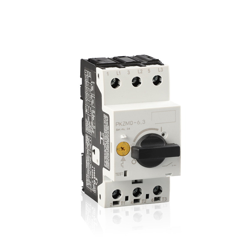
Miniature Circuit Breakers (MCBs) handle lower amperage loads. They typically rate up to 63A or 125A. Installers mount them on standard 35mm DIN rails inside combiner boxes. They utilize a bimetallic strip for thermal overload protection and a magnetic coil for instant short-circuit tripping. MCBs protect individual strings and small charge controller inputs.
Molded Case Circuit Breakers (MCCBs) handle significantly higher loads, often ranging from 100A to over 1000A. They protect main battery banks and large central inverters. MCCBs feature robust physical housings, larger terminal lugs for heavy gauge wire, and adjustable trip settings. They manage the massive current potential of commercial battery storage systems safely, providing high interrupting capacities.
Utility-scale solar farms operate at extreme voltages, often 1500V DC, to minimize transmission losses over long distances. Standard air-insulated breakers struggle with these parameters, requiring massive physical footprints to house adequate arc chutes. A High Voltage Vacuum Circuit Breaker provides the necessary protection for heavy commercial arrays in a much smaller form factor.
These devices house their electrical contacts inside a sealed vacuum chamber. Without air or gas present, plasma cannot form. The vacuum extinguishes the arc instantly upon contact separation. This technology handles high-voltage DC/AC transitions with exceptional reliability. It requires minimal maintenance, eliminates the need for gas-refill schedules, and offers high lifecycle durability, making it ideal for remote solar installations.
Active solar systems utilize moving parts to increase efficiency. Dual-axis trackers follow the sun to maximize yield. Solar-powered irrigation stations pump water using array power. These applications rely on electric induction motors. Motors draw massive inrush currents during startup, often six to eight times their normal running current for a few milliseconds.
A standard breaker will interpret this surge as a short circuit and trip immediately. A Motor Protection Circuit Breaker solves this issue. It features a specialized trip curve (often Class 10 or Class 20) that ignores brief, high-amperage spikes. It only trips upon sustained overloads or genuine dead shorts. This prevents nuisance tripping while fully protecting the motor windings from thermal damage.
Modern microgrids demand real-time data. Facility managers need granular visibility into energy production and consumption at the circuit level. A Smart WiFi and Zigbee Circuit Breaker integrates IoT technology directly into the distribution panel. These devices provide remote monitoring, automated load shedding, and detailed energy management metrics via smartphone apps or central control systems.
Engineers must evaluate the trade-offs. Network connectivity introduces potential cybersecurity vulnerabilities. Furthermore, protection must never rely solely on software. The best smart breakers retain robust mechanical fail-safes. They utilize traditional bimetallic and magnetic trip mechanisms internally. They will trip during a physical fault even if the local network goes offline entirely, ensuring baseline safety is never compromised by a router failure.
Effective protection requires strategic placement across distinct zones within the system. Omitting a disconnect in any of these zones complicates maintenance and violates electrical safety codes.
Array to Charge Controller: This zone experiences high voltage and moderate current. Breakers here isolate the incoming solar power.
Charge Controller to Battery: This zone requires precise voltage regulation. Breakers protect the wiring from battery backfeed.
Battery to Inverter: This zone handles low voltage but massive current potential. Large MCCBs are required here to handle inverter surge demands.
Inverter to AC Load Panel: This zone uses standard AC breakers to synchronize with the grid or power household loads.
The Kilo-Ampere Interrupting Capacity (kAIC) defines the maximum fault current a breaker can safely interrupt without exploding. Solar panels have a limited fault current capacity, usually only slightly higher than their operating current. Batteries, however, can discharge thousands of amps instantly during a dead short.
A large lithium iron phosphate (LiFePO4) battery bank might deliver 10,000 amps of fault current. If you install a breaker with a 5 kAIC (5,000 amps) rating on this battery, a short circuit will destroy the breaker violently, turning the housing into shrapnel. You must calculate the maximum available fault current from the battery bank and select a breaker with a kAIC rating that exceeds that number.
Solar combiner boxes sit exposed to direct sunlight on rooftops or in open fields. Internal temperatures easily exceed 60°C (140°F) during summer months. Most standard breakers use thermal mechanisms to detect overloads. Ambient heat artificially pre-heats the internal bimetallic strip. This causes the breaker to trip well below its rated capacity.
Engineers call this nuisance tripping. You must consult the manufacturer's temperature derating charts. A breaker rated for 20A at 25°C might only carry 15A at 50°C. You must upsize the breaker slightly to compensate for environmental heat, ensuring it holds the continuous solar load without exceeding wire ampacity. Proper ventilation in combiner boxes also mitigates this issue.
Battery storage systems complicate breaker selection. Current flows into the battery during charging from the solar array. Current flows out of the battery during discharging to the inverter. The current physically reverses direction. Many DC breakers are polarized. They contain magnets designed to blow an arc in one specific direction into the arc chute.
If current flows backward through a polarized breaker during a fault, the magnets blow the arc away from the chute. The arc burns through the casing and starts a fire. You must specify non-polarized (bi-directional) breakers for any circuit where current flow reverses, specifically between the battery bank and the inverter/charger.
Wiring a polarized DC breaker backward remains one of the most common and dangerous installation errors. Installers often assume the top terminals are always for incoming power. Solar wiring layouts vary. If a polarized breaker receives reverse polarity, its internal arc suppression fails completely.
Mitigation requires strict standardization practices. Read the breaker casing carefully. Look for the "+" and "-" symbols or line/load designations. Apply clear, permanent labeling to all wires during installation. Implement a secondary verification step where a different technician checks polarity with a multimeter before energizing the system.
System operators often misdiagnose breaker trips. They assume the breaker is faulty and replace it with a larger one. This action removes the safety net and invites catastrophic failure. You must differentiate between nuisance trips and genuine faults. Nuisance trips usually result from poor temperature derating or undersized initial calculations.
Genuine faults indicate system degradation. Check the wire insulation for physical damage from rodents or UV exposure. Look for water ingress in junction boxes. Perform a Megger test to verify insulation resistance. Never upsize a tripping breaker without mathematically proving the wire can handle the increased amperage.
Circuit breakers degrade over time. Continuous thermal cycling loosens terminal connections. Loose connections create high electrical resistance. High resistance generates severe localized heat, eventually melting the breaker housing. Implement a realistic maintenance schedule.
Use a thermal imaging camera to inspect breaker terminals under peak midday load. Look for temperature differentials between adjacent breakers. Any terminal showing excessive heat requires immediate attention. Power down the system, lock it out, and retorque all terminal screws to the manufacturer's specified inch-pounds using a calibrated torque screwdriver annually. This simple protocol prevents the majority of long-term hardware failures.
Selecting protective devices for photovoltaic systems requires strict engineering discipline. The safety of the property and personnel relies entirely on accurate mathematical sizing and appropriate technology selection.
Calculate the exact Isc and maximum cold-weather voltage for your specific strings before purchasing hardware.
Select the appropriate breaker category based on the load type, utilizing vacuum technology for high voltage or motor protection units for active trackers.
Apply environmental derating charts to prevent nuisance tripping in hot combiner boxes.
Verify that your final breaker selection never exceeds the maximum ampacity of your installed wiring.
Audit your current PV schematics with a certified electrical engineer to ensure full NEC or IEC compliance.
A: Start by finding the panel's Short Circuit Current (Isc) on the specification sheet. Multiply the Isc by 1.25 to account for continuous load requirements. Multiply that result by another 1.25 to meet NEC solar safety standards. Finally, round that number up to the nearest standard commercial breaker size, ensuring it does not exceed your wire's ampacity rating.
A: No. AC and DC breakers are not interchangeable. AC current has a zero-crossing point that naturally extinguishes arcs. DC current is continuous and lacks this zero-crossing. Standard AC breakers lack the magnetic blowouts and specialized arc chutes required to extinguish a DC arc, resulting in a severe fire risk.
A: The National Electrical Code (NEC) defines solar power generation as a continuous load because it operates for three or more hours straight. The code requires a 25% safety buffer (multiplying by 1.25) for all continuous loads to prevent thermal degradation of the breaker's internal components during peak sunlight hours.
A: Both serve distinct purposes. Fuses provide excellent, compact protection for individual solar strings and have high interrupt ratings. Circuit breakers provide essential resettable disconnect points. Breakers are typically used in combiner boxes, main panels, and battery banks where maintenance personnel need a reliable switch to isolate equipment safely.
A: They offer excellent real-time data, remote monitoring, and load management benefits. However, their reliability depends on network uptime. For safety, you must ensure the smart breaker retains robust mechanical fail-safes so it will still trip during a physical electrical fault even if the wireless network goes down.
A: Use them for auxiliary solar equipment containing electric motors, such as dual-axis solar trackers or solar-powered irrigation pumps. These breakers feature specialized trip curves designed to handle the brief, high inrush currents of motor startups without causing nuisance tripping, while still protecting against sustained overloads.
A: Breakers should be placed at three critical isolation points. Install them between the solar panel array and the charge controller, between the charge controller and the battery bank, and between the battery bank and the inverter. This ensures every major component can be safely isolated for maintenance.
