- All
- Product Name
- Product Keyword
- Product Model
- Product Summary
- Product Description
- Multi Field Search
Please Choose Your Language

Views: 0 Author: Site Editor Publish Time: 2026-08-12 Origin: Site


Power continuity is an absolute requirement for industrial and commercial facilities. A fraction of a second in power loss causes severe equipment damage, data corruption, and prolonged operational downtime. Safely transferring high-capacity three-phase loads between utility mains and backup generators requires precise control logic. You must prevent backfeeding, phase clashes, and catastrophic short circuits. Understanding the architecture of a 3 phase ATS wiring diagram is the essential first step. It helps in evaluating system requirements and selecting the right switching mechanisms. This knowledge ensures a fail-safe, seamless mains-to-generator implementation. Facility managers and electrical contractors rely on these schematics to map out voltage sensing lines, interlock circuits, and load distribution paths. Without a clear diagram, troubleshooting a transfer failure becomes a dangerous guessing game. We use these blueprints to verify that every relay, timer, and contactor operates in the exact sequence required to protect sensitive onsite machinery.
Architecture Fundamentals: A standard 3-phase ATS relies on distinct power and control circuits to monitor voltage across all three phases (L1, L2, L3) and neutral, utilizing either 3-pole or 4-pole configurations.
Critical Safety Mechanisms: Both electrical and mechanical interlocking are non-negotiable requirements to physically prevent the mains and generator from supplying power simultaneously.
Component Selection: Choosing between a pre-packaged Dual Power Automatic Transfer Switch and a custom-built panel using 220V/380V AC Contactors depends on load requirements, budget, and maintenance capabilities.
Modernization & Control: Integrating an Automatic Transfer Switch with Remote Control and dual-mode (auto/manual) capabilities allows for advanced facility management, predictive maintenance, and safe off-site or local manual overrides.
The physical layout of incoming power sources within the panel dictates the entire system flow. You route the utility supply to the primary breaker and the generator supply to the secondary breaker. Standard color-coding ensures compliance with regional electrical codes and prevents catastrophic cross-wiring. Technicians typically identify phases as Red, Yellow, and Blue for L1, L2, and L3 in many international standards, or Black, Red, and Blue in North American 120/208V systems. They use White or Grey for the neutral connection and Green for the equipment ground. Maintaining strict adherence to these color codes prevents phase reversal during installation.
Separating the high-current power circuit from the low-voltage control circuit is mandatory. The power circuit handles the massive amperage required to run facility loads, often utilizing heavy copper busbars or large kcmil cables. The control circuit operates on much lower currents, typically 12V DC, 24V DC, or 120V AC, to manage logic, timers, and relays. Physical segregation within the enclosure prevents electromagnetic interference from disrupting sensitive control components. We often specify NEMA 1 enclosures for indoor applications and NEMA 3R or 4X stainless steel enclosures for outdoor installations to protect this internal architecture from environmental degradation. You must maintain proper wire bending space according to NEC Article 312 to avoid stressing the cable insulation at the termination lugs.
Engineers must choose between 3-pole and 4-pole transfer switches based on grounding requirements. A 3-pole ATS features a solid, unswitched neutral. The neutral wire from the utility and the neutral wire from the generator connect directly to a common, continuous busbar. This setup works well when the backup generator shares a common ground with the utility service, simplifying the overall wiring footprint. We use this configuration primarily when the generator is not considered a separately derived system.
A 4-pole ATS switches the neutral wire alongside the three live phases. You must use a 4-pole system when the generator acts as a separately derived system with its own grounding electrode. Switching the neutral prevents ground fault sensing errors. It also stops circulating neutral currents from tripping main breakers during a power transfer. Failing to switch the neutral in a separately derived system creates parallel paths for return currents. This creates severe safety hazards for maintenance personnel and can cause nuisance tripping of ground fault relays on the main switchboard.
Phase failure relays and under-voltage monitors act as the brain of the ATS. They continuously track the health of the utility supply across all three phases. These relays detect phase loss, phase asymmetry, and severe voltage sags. If the utility voltage drops below a specific, pre-programmed threshold—usually around 80% to 85% of nominal voltage—the control logic triggers a highly coordinated sequence of events.
First, the system detects the drop in mains voltage. It waits a few seconds to confirm the outage is not a transient dip caused by a large motor starting elsewhere on the grid. This time delay prevents unnecessary generator cycling. Next, it sends a start signal to the generator. The control circuit then monitors the incoming generator voltage. It verifies frequency, usually 50Hz or 60Hz, and voltage stability before executing the final load transfer. This prevents feeding unstable, fluctuating power into sensitive facility equipment like servers, PLCs, or CNC machinery.
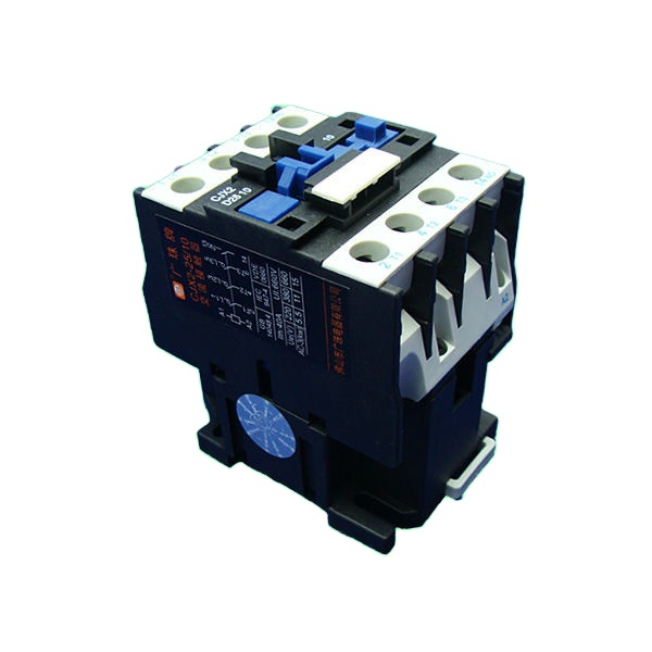
Selecting the primary switching mechanism directly impacts system longevity and performance. A 220V/380V AC Contactor offers rapid switching speeds. Contactors use electromagnetic coils to pull contacts closed, making them ideal for applications requiring frequent operations. They handle resistive loads efficiently but require careful sizing to manage the arcing associated with breaking heavy currents. When building custom panels, we rely on contactors for their modularity and ease of replacement.
Motorized molded case circuit breakers (MCCBs) provide higher fault current ratings. They withstand massive short-circuit forces better than standard contactors. MCCBs fit perfectly in heavy industrial environments where fault currents can reach extreme levels. You must evaluate utilization categories when sizing these components. AC-1 ratings apply to standard resistive heating or lighting loads. AC-3 or AC-33A ratings are strictly necessary for highly inductive motor loads that draw massive inrush currents during startup. Sizing a contactor for AC-1 when the load is primarily AC-3 will result in rapid contact degradation and eventual welding.
Time delay relays dictate the pacing of the transfer sequence. The Time Delay Engine Start (TDES) prevents nuisance generator starts during brief voltage sags, typically set between 1 and 5 seconds. The Time Delay Normal to Emergency (TDNE) allows the generator engine to reach proper operating temperature and stabilize its output before taking on the facility load. We also utilize a Time Delay Emergency to Normal (TDEN) to ensure utility power is stable before transferring back, and a Time Delay Engine Cool-down (TDEC) to let the generator run unloaded for several minutes before shutting down.
Integrating a manual/auto selector switch enables dual-mode operation. This switch allows maintenance personnel to safely force a manual changeover. If the automatic control circuit fails, technicians can still route power to the building using physical overrides. Auxiliary contacts play a major role here. They provide status indication to the panel lights and lock the control logic to prevent conflicting commands from reaching the main switching mechanisms. We wire these auxiliary contacts directly into the PLC or indicator light circuit.
Modern facilities demand advanced oversight and data logging. Smart controllers support Modbus RTU, RS485, or Ethernet communication protocols. These controllers integrate directly into building management systems. They allow operators to read holding registers containing real-time data on phase voltage, current draw, frequency, and total harmonic distortion.
Using an Automatic Transfer Switch with Remote Control provides massive operational advantages. Facility managers can initiate remote testing without stepping onto the factory floor. They can monitor real-time voltage, track transfer history, and integrate the ATS into broader SCADA networks. This connectivity enables predictive maintenance, allowing teams to replace worn contact pads or failing relays before an outage occurs. Remote control capabilities also allow operators to shed non-essential loads prior to a transfer, preventing the generator from bogging down during the initial step-load.
Mapping the power routing requires precision and strict adherence to electrical schematics. You route heavy-gauge cables from the utility and generator breakers directly to the primary switching poles. These poles connect to a common load busbar. Adequate wire bending space within the enclosure is necessary to prevent stressing the cable insulation or the physical lugs.
Proper lug torquing is an absolute requirement. Loose connections generate immense heat under high continuous current, leading to panel fires. You must size all power wires according to the maximum continuous current rating of the facility. Use a calibrated torque wrench to secure every termination on the busbar. Many installers prefer compression lugs over mechanical lugs for high-vibration environments, sealing the connections with heavy-duty heat shrink tubing.
Follow these steps for power circuit execution:
Verify all power sources are locked out and tagged out (LOTO).
Strip the incoming utility and generator cables to the exact depth specified by the lug manufacturer.
Apply a high-quality antioxidant joint compound to aluminum conductors before termination.
Insert the conductors into the primary switching poles and tighten using a calibrated torque wrench.
Route the load-side cables from the ATS common busbar to the main distribution panel.
Perform a micro-ohm resistance test across all bolted connections to verify low-resistance joints.
The control schematic follows a strict logical flow. Power moves from protective control fuses to the phase monitors. It passes through the selector switches and timer relays. Finally, the voltage reaches the contactor coils to initiate the physical switch. Every wire in this sequence must be labeled with heat-shrink markers to match the master schematic, ensuring rapid troubleshooting during an emergency.
Sending the start command requires specific dry contact wiring. The ATS control board features a normally open (NO) dry contact. When utility power fails, this contact closes. The closed circuit sends a low-voltage signal directly to the generator's engine control module (ECM). The ECM reads this signal and cranks the engine. Shielded twisted pair cables are often used for this run to prevent electrical noise from triggering false starts. We ground the shield at one end only to prevent ground loops.
Electrical interlocks prevent simultaneous power delivery. You wire the coil of the mains contactor through the normally closed (NC) auxiliary contact of the generator contactor. You repeat this in reverse for the generator side. If one contactor is pulled in, the other physically cannot receive coil voltage. This cross-wiring is the foundational safety net of any transfer system.
Mechanical interlocking adds the final layer of protection. You install a physical barrier mechanism, such as a walking-beam interlock, between the two contactors or breakers. This device physically blocks both switches from closing at the same time. Even if a technician manually pushes the contactor in while the other is engaged, the mechanical interlock stops the movement. This mitigates the risk of dead shorts and explosive phase clashes.
Factory-built units offer streamlined installation and guaranteed performance. A pre-packaged Dual Power Automatic Transfer Switch arrives fully tested. These units carry UL 1008 or IEC 60947-6-1 certifications, ensuring strict regulatory compliance. They feature a compact footprint, integrated smart controllers, and comprehensive warranty protection. The internal busbars and control wiring are optimized for thermal management.
However, they require a higher upfront investment. Proprietary parts can complicate emergency repairs if a specific circuit board fails. You have less flexibility to modify the control logic for highly unique facility requirements. If a proprietary controller fails in a remote location, you may face extended downtime waiting for a specialized replacement part from the manufacturer.
Custom panels provide ultimate flexibility. You can build a robust system using standard off-the-shelf components like DIN-rail mounted fuses, relays, and timers. This approach makes emergency repairs much easier in remote locations where proprietary parts are unavailable. You can scale the components precisely for specific inductive or resistive load types, upgrading individual contactors as facility demands grow.
The downside is the labor-intensive assembly process. Custom builds require rigorous independent testing to ensure safety. They carry higher compliance and liability risks if not designed and stamped by a certified electrical engineer. The physical footprint of a custom panel is often larger, requiring more wall space in the electrical room to accommodate discrete components.
Decision-makers must evaluate facility requirements when choosing a system architecture. The environment, available technical expertise, and load profiles should drive the final specification.
| Evaluation Criteria | Pre-Packaged Dual Power ATS | Custom Contactor-Based ATS |
|---|---|---|
| Regulatory Compliance | High (UL 1008 / IEC certified out of the box) | Variable (Requires independent engineering sign-off) |
| Repairability | Low (Relies on proprietary manufacturer parts) | High (Uses standard off-the-shelf relays and timers) |
| Installation Speed | Fast (Pre-wired and factory tested) | Slow (Requires extensive field wiring and testing) |
| Ideal Application | Hospitals, data centers, commercial high-rises | Agricultural facilities, remote mining operations |
Wiring the generator phase sequence incorrectly introduces massive operational risks. If L1, L2, and L3 do not match the utility sequence, three-phase motors will run backward. This reversal can destroy pumps, compressors, and conveyor systems instantly. Technicians must use a phase rotation meter during commissioning to verify both sources match perfectly before enabling the automatic transfer sequence.
You must install in-phase monitors to prevent out-of-sync transfers. Highly inductive loads generate residual voltage when disconnected. If the ATS transfers power while the generator and residual motor voltages are out of phase, the resulting transient torque can shear motor shafts or violently trip main breakers. In-phase monitors ensure the switch only occurs when the phase angles of both sources align.
Contact welding occurs when high inrush currents or short circuits melt the switching contacts together. If a contact welds shut, the mechanical interlock may jam, disabling the entire system. This leaves the facility vulnerable to continuous power loss or catastrophic backfeeding if the interlock fails entirely.
Mitigate this risk by specifying contactors with appropriate short-circuit withstand ratings and robust arc chutes. Implement proper time delays during the transfer sequence. A programmed neutral-position delay allows residual voltage to decay completely before the switch connects to the alternate power source. This drastically reduces arc flash hazards, extinguishes electrical arcs safely, and extends the operational lifespan of the contact pads. Technicians must always wear appropriate PPE as dictated by NFPA 70E when working near these panels.
Rigorous testing ensures the system performs flawlessly during an actual outage. Begin with dead-bus testing to verify wire routing without live voltage. Use a multimeter to check the continuity of the electrical interlocks. Next, perform manual transfer testing using the dual-mode selector switch to confirm mechanical linkages operate smoothly without binding.
Execute the following commissioning sequence:
Perform a visual inspection of all torque marks and heat-shrink labels.
Conduct insulation resistance testing on all power cables.
Apply control voltage and verify timer relay settings.
Simulate a utility failure by opening the main upstream breaker.
Verify the generator starts and reaches nominal voltage and frequency.
Confirm the ATS transfers the load smoothly without excessive arcing.
Restore utility power and verify the re-transfer and generator cool-down sequence.
Routine load bank testing is also mandatory. It ensures the generator engine and the ATS power poles can handle the facility's peak demand without overheating. Testing with both resistive and reactive load banks provides the most accurate simulation of actual facility conditions.
Conduct a comprehensive load study to determine your exact continuous and peak inrush current requirements before selecting components.
Verify whether your generator installation requires a switched neutral (4-pole) or solid neutral (3-pole) configuration based on local grounding codes.
Audit your current panel space to ensure adequate physical segregation between high-voltage power cables and low-voltage control wiring.
Schedule a consultation with a licensed electrical engineer to review your proposed schematics against regional safety standards.
A: A 3-phase diagram routes three distinct live wires (L1, L2, L3) and a neutral, requiring 3-pole or 4-pole switching mechanisms. A single-phase diagram only manages one live wire and a neutral. The 3-phase control circuit is also more complex, utilizing phase failure relays to monitor all three lines simultaneously for voltage drops or phase loss.
A: The contactor acts as the primary physical switching mechanism. It uses an electromagnetic coil to pull high-capacity electrical contacts closed. This action connects the facility load to either the utility mains or the backup generator. Contactors allow for rapid, automated switching based on commands from the control circuit logic.
A: Yes. A properly designed system includes a manual/auto selector switch and a physical manual override handle. If the smart controller or remote network fails, technicians can manually force the mechanical linkages to transfer power safely without relying on the electronic logic board.
A: Mechanical interlocking provides a physical, fail-safe barrier that prevents both the utility and generator switches from closing at the same time. Without it, a control failure could cause simultaneous connection, resulting in a catastrophic dead short, explosive arc flash, and severe equipment destruction.
A: You wire a dedicated two-wire circuit from the normally open (NO) dry contacts on the ATS control board to the generator's engine control module. When the ATS detects a utility failure, the dry contact closes, completing the circuit and signaling the generator to start cranking.
A: If you use a solid neutral (3-pole) when a switched neutral (4-pole) is required, you create multiple ground paths. This causes circulating neutral currents that trigger ground fault circuit interrupters (GFCIs) erroneously. It compromises the safety of the facility's grounding system during a power transfer.
A: A 3-pole ATS switches only the three live phases (L1, L2, L3) while keeping the neutral wire permanently connected to a common busbar. A 4-pole ATS switches the three live phases plus the neutral wire, completely isolating the generator power source from the utility power source.
