- All
- Product Name
- Product Keyword
- Product Model
- Product Summary
- Product Description
- Multi Field Search
Please Choose Your Language

Views: 0 Author: Site Editor Publish Time: 2026-08-18 Origin: Site


Direct current power lacks a zero-crossing point. This physical reality means continuous arcs destroy equipment rapidly if a fault hits a high-capacity battery bank. System integrators often miscalculate continuous loads, inverter surges, or short-circuit currents. These errors cause nuisance tripping, melted terminals, and battery fires. You need a strict, code-compliant framework to calculate exact amperage and voltage requirements. Selecting the right protection device keeps energy storage systems safe and operational. This guide breaks down the exact formulas, specification checks, and installation realities you need to size battery protection devices accurately on the job site. When you stand in front of a 48V lithium rack, you realize the raw energy waiting to escape. A simple dropped wrench can vaporize copper instantly. Guessing breaker sizes based on nominal ratings fails. We rely on hard math and proven field practices to match the breaker to the exact battery chemistry and load profile.
The 1.25x Multiplier Rule: Standard sizing dictates that the breaker rating must be at least 125% of the maximum continuous charging or discharging current to prevent thermal degradation.
Rounding Up to Standard Sizes: After calculating the required amperage, always round up to the next highest commercially available standard breaker size to avoid operating at the absolute thermal limit.
Voltage Headroom is Critical: A breaker must be rated for the maximum equalization or charging voltage of the battery chemistry, not just the nominal system voltage (e.g., a 48V nominal system can exceed 58V during charging).
Interrupting Capacity Matters: The breaker must safely clear the maximum short-circuit current the battery bank can deliver, which often dictates the choice between a standard MCB and a heavier-duty alternative.
AC Breakers are Unsafe for DC: Repurposing AC-rated breakers for DC battery applications violates electrical codes and fails to extinguish DC arcs, creating severe fire hazards.
Alternating current naturally extinguishes electrical arcs. AC voltage crosses zero volts 120 times per second. This zero-crossing briefly halts current flow. The arc breaks naturally. Direct current operates differently. DC provides a constant, unyielding flow of energy. When you pull apart contacts under a heavy DC load, the current simply jumps the gap. It creates a sustained plasma arc. A 48V battery bank easily sustains an arc hot enough to melt copper. It will ignite surrounding plastics in seconds. A dedicated DC miniature circuit breaker contains specific internal mechanisms to fight this physical reality. These devices feature magnetic blowout coils. They also use specialized arc chutes. The magnetic field forces the plasma arc away from the contacts. It pushes the arc into the chutes. The chutes stretch the arc, cool it, and finally break it. Standard breakers lack these magnetic components. If you open a standard breaker under a DC load, the arc stays right on the contacts until the housing melts.
Using AC breakers in DC battery circuits guarantees failure. It violates every major electrical code worldwide. When an AC breaker attempts to interrupt a DC fault, the contacts open, but the arc remains. The sustained plasma arc generates immense heat. Within seconds, the internal contacts weld completely shut. Once welded, the breaker cannot trip. The fault current continues to flow freely from the battery bank. This leads directly to melted wiring insulation and enclosure fires. Repurposing AC equipment voids all manufacturer warranties. It exposes installers to severe liability in the event of a system fire. You must verify the DC rating stamped directly on the breaker housing before installation.
Battery systems are inherently bidirectional. Energy flows into the battery during charging cycles from solar arrays or the grid. Energy flows out of the battery during discharge cycles to power inverters and DC loads. The protection device must handle current flowing in both directions safely. Some older or specialized breakers are strictly polarized. They only extinguish arcs effectively when current flows in one specific direction. Modern battery systems require non-polarized DC breakers. A non-polarized breaker protects the circuit regardless of the current direction. This ensures the trip curve remains accurate whether the battery is absorbing a heavy charge or delivering a massive surge to start a motor.
System designers often debate between fuses and breakers. The best practice involves using both for different purposes. Fuses provide excellent catastrophic short-circuit protection. A Class T fuse reacts instantly to massive fault currents. Fuses are one-time-use items. They offer no manual disconnect functionality. A DC breaker provides resettable overload protection. It trips during sustained overcurrent events, like an inverter drawing too much power. You can easily reset the breaker once you clear the fault. The breaker acts as a manual isolation switch. You can physically switch off the breaker to perform maintenance safely. We follow a strict sequence when combining these devices:
Install a Class T fuse directly at the positive battery terminal to handle catastrophic short circuits.
Route the heavy gauge cable from the fuse block to the DC breaker enclosure.
Mount the breaker on a secure DIN rail, ensuring adequate spacing for thermal dissipation.
Connect the load side of the breaker to the inverter or charge controller.
Proper sizing begins with a strict mathematical formula. You cannot simply match the breaker size to the load size. Electrical codes require a safety margin for continuous loads. A continuous load operates for three hours or more. The formula is simple: Breaker Size = Maximum Continuous Current × 1.25. This 1.25x multiplier provides a 25% safety margin. It prevents the breaker from operating at its absolute thermal limit, which causes nuisance tripping. Consider a DC load that draws 50 amps continuously. Multiply 50A by 1.25 to get 62.5 amps. You cannot buy a 62.5A breaker. You must round up to the next highest standard commercial size. In this scenario, you select a 63A breaker. Never round down, as this guarantees premature thermal tripping.
| Continuous Load (Amps) | 1.25x Calculation | Minimum Standard Breaker Size |
|---|---|---|
| 20A | 25A | 25A or 32A |
| 40A | 50A | 50A |
| 50A | 62.5A | 63A |
| 80A | 100A | 100A |
| 100A | 125A | 125A |
Different system components demand different sizing strategies. Inverters present unique challenges due to surge loads. A 6500W inverter running on a 48V battery bank draws roughly 135 amps continuously. Inverters often feature a surge rating double their continuous output. If that inverter surges to 13000W to start a well pump, the current spikes to 270 amps for a few seconds. You must select a breaker with an appropriate trip curve. Curve C or Curve D breakers tolerate temporary motor-starting surges without nuisance tripping. Charge controllers require a different approach. Solar charge controllers output a steady, continuous current. If you install an 80A MPPT charge controller, it requires a dedicated breaker sized for its maximum output. Multiply 80A by 1.25 to get 100A. You install a 100A breaker between the controller and the battery to protect the wiring and isolate the component.
Amperage is only half the equation. You must also calculate the maximum system voltage. Battery nominal voltage is highly misleading. A 48V nominal system rarely operates at exactly 48 volts. Different battery chemistries require different charging parameters. The breaker's maximum DC voltage rating must sit comfortably above the highest possible system voltage. Insufficient voltage headroom compromises the breaker's ability to extinguish arcs. We see specific peak voltages across different chemistries in the field:
12V Nominal Lead-Acid: Peaks around 14.8V during equalization charges.
24V Nominal LiFePO4: Requires absorption charging at 29.2V.
48V Nominal LiFePO4: Reaches 58.4V at the top of the charge cycle.
48V Nominal NMC Lithium: Can exceed 54.6V depending on the exact cell configuration.
If your system peaks at 58.4V, a breaker rated for only 48V DC is unsafe. You must select a breaker rated for at least 60V DC. Ratings of 80V or 125V DC provide even better safety margins.
Overload protection handles slight current excesses. Short-circuit protection handles catastrophic failures. If a metal tool drops across the battery terminals, the current spikes instantly. You must calculate the prospective short-circuit current of your specific battery bank. Multiply the battery's amp-hour (Ah) rating by its maximum short-circuit C-rate. A high-performance 300Ah battery bank might deliver 3000 amps during a dead short. The breaker must survive this event without exploding. You must check the breaker's Icu (rated ultimate short-circuit breaking capacity) and Ics (rated service short-circuit breaking capacity). The Icu rating must exceed the battery's maximum fault potential. If the battery can deliver 3000A, a breaker with a 6000A (6kA) breaking capacity provides excellent protection.
Selecting the correct number of poles depends entirely on system grounding. Many mobile and off-grid battery systems utilize a negative ground. The negative battery terminal bonds directly to the vehicle chassis or earth ground. In a negatively grounded system, you only need a single-pole breaker. You install this 1-pole breaker on the positive, ungrounded conductor. Many modern energy storage systems operate as floating or ungrounded systems. Neither the positive nor the negative terminal connects to ground. In these systems, a fault can occur on either leg. You must use a 2-pole breaker for floating systems. A 2-pole breaker disconnects both the positive and negative legs simultaneously. This guarantees complete isolation of the battery bank during a fault or maintenance procedure.
Miniature circuit breakers rely on thermal-magnetic trip mechanisms. The thermal portion uses a bimetallic strip that bends as it heats up from current flow. Ambient temperature heavily influences this mechanism. Manufacturers calibrate breakers at a specific reference temperature, usually 30°C (86°F). Battery enclosures, telecom cabinets, and EV chargers often exceed this temperature. If the ambient temperature reaches 50°C (122°F), the breaker will trip prematurely. You must apply manufacturer derating tables to avoid this. If the enclosure runs hot, you may need to upsize the breaker slightly to compensate for the ambient temperature. Proper ventilation and spacing between breakers on the DIN rail also reduce localized heat buildup.
| Ambient Temperature | 63A Breaker Actual Rating | 125A Breaker Actual Rating |
|---|---|---|
| 30°C (Reference) | 63.0A | 125.0A |
| 40°C | 59.8A | 118.7A |
| 50°C | 56.7A | 112.5A |
| 60°C | 53.5A | 106.2A |
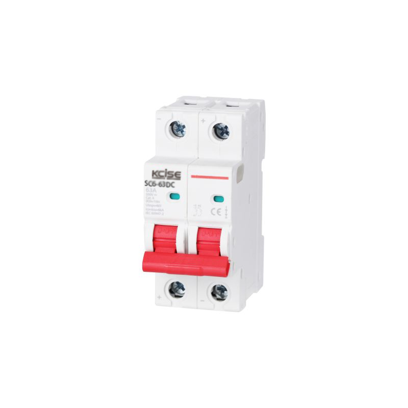
Low-to-medium load applications require precise, compact protection. The SC6-63DC DC Miniature Circuit Breaker fits these scenarios perfectly. This breaker handles loads up to 63 amps safely. It works exceptionally well for small off-grid solar setups, cabin power systems, and DC lighting circuits. We frequently use these breakers as charge controller disconnects for smaller arrays. They also serve well in EV charger control circuits where auxiliary DC power requires protection. The compact DIN-rail mounting saves valuable space in small enclosures. When sizing for this breaker, ensure your continuous load does not exceed 50 amps (50A x 1.25 = 62.5A). This leaves enough headroom to utilize the 63A rating safely without risking thermal degradation.
High-capacity residential and commercial solar storage systems demand heavier hardware. The SC6-125 125A 2-Pole DC MCB bridges the gap between small electronics and industrial power. A 125A rating provides substantial capacity for 48V nominal battery banks. This breaker handles continuous loads up to 100 amps (100A x 1.25 = 125A). This translates to roughly 4800 watts of continuous inverter draw. The 2-pole design makes it perfect for isolating heavy-duty inverters in floating battery systems. It disconnects both the positive and negative cables simultaneously. This ensures complete safety during inverter maintenance. The robust internal arc chutes handle the higher fault currents associated with larger lithium battery banks.
Miniature circuit breakers have physical limitations. When your system exceeds a 125A continuous load, you cross a critical threshold. Large whole-home inverters draw massive DC currents. A 12kW inverter at 48V draws over 250 amps continuously. You cannot protect this with a standard MCB. You must upgrade to a DC Molded Case Circuit Breaker for Batteries. MCCBs feature significantly larger physical footprints. They offer massive terminal lugs capable of accepting 4/0 AWG or larger battery cables. MCCBs often feature adjustable thermal-magnetic trip units. You can dial in the exact trip amperage to match your battery manufacturer's specifications. MCCBs provide vastly superior short-circuit breaking capacities, often exceeding 20kA. This capacity is mandatory for massive industrial battery racks.
| Feature | DC Miniature Circuit Breaker (MCB) | DC Molded Case Circuit Breaker (MCCB) |
|---|---|---|
| Maximum Current Rating | Typically up to 125A | From 100A up to 1000A+ |
| Short-Circuit Capacity (Icu) | Standard (usually 6kA to 10kA) | Very High (often 20kA to 100kA) |
| Physical Footprint | Compact, DIN-rail mounted | Large, panel or backplate mounted |
| Trip Unit Adjustability | Fixed trip settings | Adjustable thermal and magnetic dials |
| Cable Lug Capacity | Small to medium AWG wire | Large AWG to heavy busbars |
Low-voltage, high-amperage DC systems require massive cables to minimize voltage drop. A 100A DC circuit often requires 2 AWG or 1/0 AWG copper wire. A major implementation reality is that these large cables simply will not fit into standard MCB terminals. Forcing oversized wire into a small terminal breaks the copper strands. Trimming strands to make the wire fit reduces the cable's ampacity and creates a severe fire hazard. You must use proper termination methods to maintain secure, low-resistance connections:
Reducer Pins: Crimp these onto oversized cables to step down the physical diameter while maintaining full ampacity.
Busbar Adapters: Bolt heavy ring terminals to a copper busbar, then run a properly sized short jumper to the breaker.
High-Strand Ferrules: Compress fine-stranded battery cable into a solid block to prevent strand breakage inside the lug.
Regulatory compliance dictates strict rules for battery disconnects. Overcurrent protection must sit as close to the battery terminals as physically possible. This minimizes the length of unprotected cable between the battery and the breaker. Codes typically require the breaker to be within 18 inches of the battery bank. Strict labeling requirements apply. You must label the DC breaker with its maximum operating voltage, maximum continuous current, and short-circuit interrupting capacity. The label must clearly state "Battery Disconnect" to assist emergency responders. Failure to follow these placement and labeling codes results in failed inspections and denied insurance claims.
Installers repeat the same sizing mistakes constantly. The most dangerous error involves ignoring battery discharge curves. As a battery discharges, its voltage drops. To maintain the same wattage output to the inverter, the amperage draw must increase. If you size the breaker based on the peak fully-charged voltage, it will trip when the battery runs low and draws more amps. Always calculate maximum amperage using the battery's lowest cutoff voltage. Another frequent mistake is failing to round up to the next standard breaker size, causing the breaker to run too hot. Installers often fail to torque the breaker terminals to the manufacturer's exact specifications. Loose terminals create electrical resistance. This resistance generates heat, which transfers into the breaker and causes false thermal tripping. Always use a calibrated torque screwdriver.
| Wire Gauge (AWG) | Recommended Torque (Nm) | Recommended Torque (in-lbs) |
|---|---|---|
| 8 AWG | 2.5 Nm | 22 in-lbs |
| 6 AWG | 3.0 Nm | 27 in-lbs |
| 4 AWG | 3.5 Nm | 31 in-lbs |
| 2 AWG | 4.0 Nm | 35 in-lbs |
Audit your maximum inverter draw and calculate the surge amperage to establish your baseline load.
Verify your battery chemistry's peak charging voltage to ensure your selected breaker has adequate voltage headroom.
Cross-reference your required wire gauge with the breaker's terminal capacity to plan for reducer pins or busbars.
Consult local electrical codes and torque all terminal connections to the manufacturer's exact specifications before commissioning the system.
A: Breaker size depends on the maximum discharge rate of your BMS or the connected inverter's draw, not the Ah capacity. If your inverter draws 100A continuously, multiply by 1.25 to get 125A. You select a 125A DC breaker. Always size for the load and the wire, ensuring it never exceeds the battery's safe discharge limits.
A: No. Using an AC breaker for DC applications creates a severe fire hazard. AC breakers lack the magnetic blowout coils and specialized arc chutes required to extinguish sustained DC plasma arcs. Under a DC fault, an AC breaker's contacts will weld shut. This fails to stop the current and destroys the equipment.
A: Take the maximum continuous current your system will draw or charge with, and multiply it by 1.25. This provides a mandatory 25% safety margin to prevent thermal degradation. For example, a 40A continuous load requires a 50A calculation. You then select a 50A standard breaker to handle the load safely.
A: A Miniature Circuit Breaker (MCB) is compact, mounts on a DIN rail, and handles currents up to 125A. A Molded Case Circuit Breaker (MCCB) is physically larger and mounts to a backplate. MCCBs handle currents from 100A to over 1000A, accept massive battery cables, and offer vastly higher short-circuit interrupting capacities.
A: You should use both. A high-interrupting-capacity fuse at the battery terminal protects against catastrophic short circuits. A DC MCB installed downstream provides resettable overload protection. The breaker also acts as a convenient manual disconnect switch for system maintenance and troubleshooting.
A: In a standard negatively grounded system, install the single-pole breaker on the positive ungrounded conductor. Many modern battery systems operate as ungrounded or floating systems. For floating systems, you must use a 2-pole DC breaker to disconnect both the positive and negative legs simultaneously.
A: Common causes include an undersized breaker failing to handle inverter surge loads. High ambient temperatures also cause premature thermal derating. Loose terminal connections create localized heat, triggering a false thermal trip. Finally, as battery voltage drops under load, amperage increases, which easily exceeds the breaker's rating if sized incorrectly.
