- All
- Product Name
- Product Keyword
- Product Model
- Product Summary
- Product Description
- Multi Field Search
Please Choose Your Language

Views: 0 Author: Site Editor Publish Time: 2026-08-29 Origin: Site


Sizing a circuit breaker correctly prevents catastrophic electrical failures. Incorrect sizing forces a dangerous compromise on the job site. If you oversize the breaker, you risk thermal damage and electrical fires because the wire melts before the breaker trips. If you undersize it, you face constant nuisance tripping, leading to expensive operational downtime. Modern electrical specification requires precision. Engineers must balance baseline amperage requirements with high inrush currents, environmental derating factors, and strict compliance standards.
This guide provides a systematic, engineering-first framework for specifying a miniature circuit breaker. We move step-by-step from baseline load calculations and system voltage confirmation to precise trip curve selection. You will learn how to evaluate advanced application requirements and apply environmental derating formulas to ensure safe, reliable circuit protection.
Proper sizing requires calculating the continuous load and applying the standard 80% rule (or 125% of continuous load) to determine the baseline amperage rating.
Selecting between B, C, and D curves is strictly dictated by the load's inrush current profile, not just the steady-state wattage.
Modern installations frequently require specialized variants, such as a Solar DC Miniature Circuit Breaker for photovoltaic systems or an RCBO Miniature Circuit Breaker for combined earth-fault protection.
Ambient temperature, altitude, and enclosure grouping must be factored into the final specification to prevent premature thermal tripping.
Electrical loads fall into two distinct categories: continuous and non-continuous. National and international electrical codes define a continuous load as any circuit operating at maximum current for three hours or more. Lighting systems in commercial buildings, server racks, and HVAC units represent typical continuous loads. Non-continuous loads operate intermittently. Examples include power outlets used for hand tools, breakroom appliances, or temporary maintenance equipment.
You must apply the 80% rule when sizing protection for continuous operations. A breaker should only carry 80% of its maximum rated amperage under continuous load. Alternatively, you can calculate 125% of the continuous load to find the minimum breaker size. Thermal-magnetic breakers generate internal heat during operation. If you run a 20A breaker at exactly 20A for several hours, the internal bimetallic strip will eventually warp and trip the circuit due to heat accumulation. Sizing the breaker to 80% capacity prevents this premature thermal tripping. For example, a circuit drawing a continuous 16 amps requires a 20-amp breaker (16A x 1.25 = 20A).
Accurate load calculation relies on fundamental electrical formulas. You must convert known wattage into amperage to select the correct breaker size. Field technicians cannot rely on guesswork when dealing with complex loads. For single-phase alternating current (AC) loads, use the standard formula: I = P / (V × cos φ). In this equation, "I" represents the current in amps, "P" is the power in watts, "V" is the system voltage, and "cos φ" is the power factor.
Three-phase AC systems require a slightly different approach to account for phase distribution. Use the formula: I = P / (√3 × V × cos φ). The square root of three (approximately 1.732) factors in the three-phase power delivery. The power factor (cos φ) dictates the true power drawn in real-world industrial environments. While purely resistive loads like electric heaters have a power factor of 1.0, inductive loads like motors or transformers often have a power factor between 0.7 and 0.85. Ignoring the power factor will result in an undersized breaker calculation, leading to immediate tripping upon startup.
Once you calculate the theoretical amperage, you must map this figure to standard off-the-shelf breaker sizes. Manufacturers produce breakers in standardized amperage ratings. Common sizes include 6A, 10A, 16A, 20A, 25A, 32A, 40A, 50A, and 63A. You always round up to the next available standard size after applying your 125% continuous load multiplier.
Follow these exact steps when mapping your calculated load to a physical breaker:
Identify the total connected wattage on the circuit.
Determine if the load is continuous (runs for 3+ hours) or non-continuous.
Apply the appropriate AC formula (single-phase or three-phase) to find the raw amperage.
Multiply the raw amperage by 1.25 if the load is continuous.
Select the next highest standard breaker size available from the manufacturer.
The table below provides a quick-reference conversion for typical single-phase (230V) and three-phase (400V) loads assuming a power factor of 0.9. This streamlines field specification and helps engineers quickly identify the necessary breaker rating.
| Load Power (kW) | Single-Phase (230V) Current | Three-Phase (400V) Current | Recommended Breaker Size (Standard) |
|---|---|---|---|
| 1 kW | 4.8 A | 1.6 A | 6A (1P) / 6A (3P) |
| 3 kW | 14.5 A | 4.8 A | 20A (1P) / 6A (3P) |
| 5 kW | 24.1 A | 8.0 A | 32A (1P) / 10A (3P) |
| 10 kW | 48.3 A | 16.0 A | 63A (1P) / 20A (3P) |
| 15 kW | 72.4 A (Requires MCCB) | 24.1 A | N/A / 32A (3P) |
Amperage alone does not dictate breaker selection. You must verify the system voltage and match it to the breaker's rated voltage. Standard distribution systems operate at 120V/240V for single-phase or 400V/480V for three-phase applications. The breaker must be rated for the maximum operational voltage of the circuit.
Voltage transients pose a significant danger to electrical infrastructure. The maximum operational voltage must never exceed the breaker's dielectric limits. If a breaker is rated for 240V, installing it on a 480V system compromises its internal insulation. During a fault, the higher voltage can jump the internal contacts, sustaining an electrical arc. This failure to extinguish the arc destroys the breaker and often leads to severe panel fires. Always check the impulse withstand voltage (Uimp) rating on the datasheet to ensure the breaker can handle temporary voltage spikes common in industrial environments.
Breaking capacity defines the maximum fault current a breaker can safely interrupt without destroying itself. This is measured in kilo-amperes (kA). Standard residential applications typically require a 6kA breaking capacity. Commercial and industrial installations demand higher ratings, usually starting at 10kA and scaling up to 15kA or more.
You must calculate the prospective short-circuit current (PSCC) at the exact point of installation. The PSCC depends on the size of the upstream utility transformer and the length and gauge of the wire feeding the panel. If the calculated PSCC at the panel is 8kA, installing a 6kA breaker creates a severe safety hazard. During a dead short, the 8kA fault current will weld the internal contacts of the 6kA breaker together, allowing the massive current to flow unchecked until upstream protection kicks in or the wiring melts.
| Facility Type | Typical PSCC Range | Recommended Minimum kA Rating |
|---|---|---|
| Residential Housing | 3kA - 5kA | 6kA |
| Light Commercial / Retail | 6kA - 8kA | 10kA |
| Heavy Industrial / Manufacturing | 10kA - 14kA | 15kA |
Alternating current (AC) and direct current (DC) behave very differently during a fault. AC voltage naturally crosses zero volts 50 or 60 times per second. This zero-crossing point helps the breaker extinguish the electrical arc naturally. DC voltage flows continuously without ever crossing zero. Breaking a DC circuit under load creates a sustained, aggressive plasma arc that is incredibly difficult to extinguish.
You must specify a dedicated Solar DC Miniature Circuit Breaker for photovoltaic arrays and battery storage systems. These specialized breakers feature robust arc chutes and magnetic blowout coils designed specifically to force the DC arc away from the contacts and extinguish it. They also support higher voltage thresholds, often up to 1000V DC. You must also pay attention to polarized versus non-polarized configurations. Polarized DC breakers must be wired with strict adherence to the flow of current, while non-polarized versions allow bi-directional current flow, making them ideal for battery systems that both charge and discharge.
Selecting the correct pole count depends entirely on your distribution system and the specific load. A single-pole (1P) breaker protects a single live wire and is standard for basic 120V or 230V lighting and receptacle circuits. A two-pole (2P) breaker connects two live wires, commonly used for 240V single-phase appliances like water heaters or large air conditioners.
Three-phase systems require three-pole (3P) breakers to protect all three live phases simultaneously. If a fault occurs on any single phase, the internal trip mechanism ensures all three poles open together, preventing single-phasing damage to three-phase motors. A four-pole (4P) breaker protects the three live phases plus the neutral wire. You specify 4P breakers in systems where complete isolation of the circuit, including the neutral, is required for maintenance safety or specific grounding arrangements.
The trip curve dictates how the breaker responds to short-duration inrush currents. Type B curves are the most sensitive standard option. They are calibrated to trip when the current reaches 3 to 5 times the rated full-load amperage. If you have a 10A Type B breaker, it will trip instantly if the current spikes between 30A and 50A.
You specify Type B breakers for purely resistive loads or circuits with minimal inrush current. Ideal use cases include standard residential wiring, basic incandescent lighting circuits, and IT equipment. These loads draw a steady current upon startup, allowing the sensitive magnetic trip mechanism to provide rapid protection against minor short circuits without causing nuisance tripping. Using a Type B curve on a motor circuit will result in immediate tripping the moment the motor attempts to start.
Type C curves offer a moderate delay, tripping at 5 to 10 times the rated current. A 10A Type C breaker will allow a brief surge up to 50A to 100A before the magnetic mechanism engages. This delay is measured in milliseconds, providing enough time for a motor to start without compromising short-circuit protection.
You should select Type C breakers for inductive loads. Ideal applications include commercial lighting banks, small electric motors, exhaust fans, and residential HVAC systems. When an electric motor starts, it requires a massive surge of energy to overcome physical inertia. A Type B breaker would interpret this normal startup surge as a fault and trip immediately. The Type C curve accommodates this temporary inrush, making it the most common choice for general commercial applications.
Type D curves are designed for extreme inrush scenarios. They trip between 10 and 20 times the rated current. A 10A Type D breaker will tolerate a massive temporary spike of 100A to 200A. This curve provides the highest level of tolerance for temporary overcurrents.
You must specify Type D breakers for heavy industrial applications. Ideal use cases include large industrial motors, heavy-duty transformers, welding equipment, and medical X-ray machines. These devices draw enormous amounts of power for a fraction of a second upon startup. Using anything other than a Type D curve in these scenarios guarantees constant, frustrating nuisance tripping and operational failure. However, because Type D breakers allow such high fault currents before tripping, the downstream wiring must be sized appropriately to handle the thermal stress of a delayed trip.
Highly specific engineering requirements demand specialized trip curves. The K-curve is optimized specifically for motor protection. It trips between 8 and 12 times the rated current. It offers a more precise thermal trip profile than a Type D curve, protecting sensitive motor windings from sustained, low-level overloads while still allowing for high startup surges.
The Z-curve provides ultra-sensitive protection. It trips at just 2 to 3 times the rated current. You specify Z-curve breakers exclusively for highly sensitive semiconductor protection, instrumentation circuits, and delicate medical electronics. These components cannot tolerate even minor current spikes, requiring the absolute fastest magnetic trip response available. Installing a Z-curve breaker on a standard lighting circuit will cause it to trip every time a switch is flipped due to the microscopic inrush of the bulbs.
Modern electrical panels often face severe space constraints. Traditionally, engineers installed a standard breaker for overcurrent protection alongside a separate Residual Current Device (RCD) for earth-leakage protection. Combining these two functions into a single RCBO Miniature Circuit Breaker streamlines panel design and improves safety.
The primary benefit of an RCBO is space-saving. It occupies half the DIN-rail space of a separate MCB and RCD combination. Furthermore, an RCBO isolates earth faults to a single circuit. If a ground fault occurs on a lighting circuit, only that specific RCBO trips, leaving the rest of the facility powered. The trade-off involves replacement costs. If either the overcurrent mechanism or the leakage detection fails, you must replace the entire integrated unit. When wiring an RCBO, technicians must ensure the neutral pigtail is correctly terminated to the neutral bus bar to guarantee the earth-leakage detection functions properly.
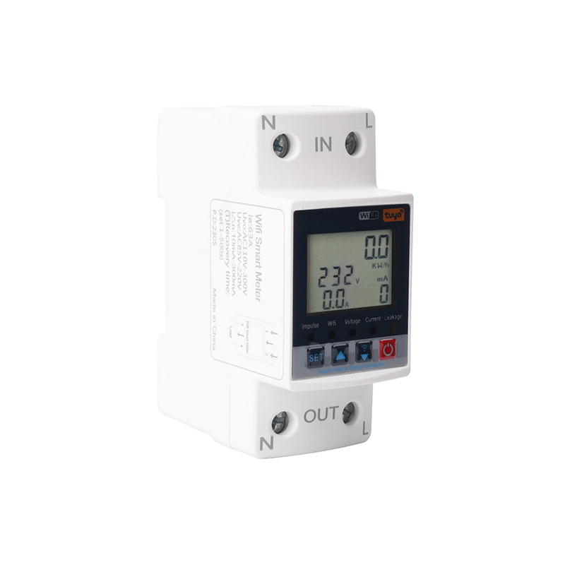
Facility managers increasingly demand granular control over energy consumption. Integrating a WiFi Smart Miniature Circuit Breaker provides enterprise-level value through IoT-enabled energy monitoring and remote load management. These devices allow operators to track real-time power usage, schedule automated shutdowns for non-essential loads, and receive instant alerts regarding circuit faults.
When specifying smart breakers for critical infrastructure, you must address cybersecurity and fail-safe mechanisms. Reputable smart breakers utilize encrypted communication protocols to prevent unauthorized remote switching. More importantly, the physical thermal-magnetic protection mechanism operates entirely independently of the smart module. If the facility loses network connectivity or the internal WiFi chip fails, the breaker still provides guaranteed physical protection against short circuits and overloads. The internal contactor relay handles the remote switching, while the traditional bimetallic strip and magnetic coil handle the safety tripping.
Thermal-magnetic breakers rely on a bimetallic strip that bends as it heats up. Because this mechanism is temperature-sensitive, manufacturers calibrate breakers at a specific reference temperature, typically 30°C or 40°C. If you install the breaker in an environment matching the reference temperature, it will carry its full rated current.
Installing breakers in high-heat environments requires strict ambient temperature derating. If you place a 32A breaker inside an outdoor solar enclosure where summer temperatures reach 50°C, the ambient heat pre-warps the bimetallic strip. The breaker will trip well below its 32A rating. You must consult the manufacturer's derating tables. At 50°C, a 32A breaker might only be rated to carry 26A safely. You must upsize the breaker to compensate for this environmental heat.
| Ambient Temperature | Derating Multiplier (Approximate) | Effective Capacity of a 32A Breaker |
|---|---|---|
| 30°C (Reference) | 1.00 | 32.0 A |
| 40°C | 0.90 | 28.8 A |
| 50°C | 0.81 | 25.9 A |
| 60°C | 0.73 | 23.3 A |
Mounting multiple breakers flush against each other on a DIN rail creates a mutual heating effect. The breakers cannot dissipate heat efficiently through their sides. When grouping multiple heavily loaded breakers, you must apply a grouping derating factor. Typically, grouping three or more breakers requires reducing their effective load capacity by 10% to 20% to prevent localized overheating within the panel. If you have the space, leaving a small gap or installing dummy blanks between heavily loaded breakers mitigates this issue.
Altitude also impacts breaker performance. Installations above 2000 meters face reduced air density. Thinner air cools the breaker less efficiently, exacerbating thermal issues. Furthermore, thinner air has a lower dielectric strength, meaning it is less effective at insulating against electrical arcs. Manufacturers provide specific altitude derating multipliers to adjust both the current carrying capacity and the maximum voltage rating for high-altitude projects. Failing to account for altitude in mountain installations leads to premature failure and arc flash hazards.
Miniature circuit breakers have strict physical and electrical limitations. They are designed for sub-circuit distribution. The hard limit for a standard modular breaker is typically a maximum current rating of 63A to 125A, with a maximum short-circuit breaking capacity of 10kA to 15kA. Attempting to push these devices beyond these limits results in catastrophic failure.
Engineers must transition from an MCB to a Molded Case Circuit Breaker (MCCB) when the load exceeds these thresholds. You specify an MCCB when the continuous load surpasses 125A, or when the prospective short-circuit current at the panel exceeds 15kA. MCCBs scale up to 2500A for heavy industrial distribution. They also offer adjustable trip settings, allowing engineers to fine-tune the thermal and magnetic response to match highly specific heavy machinery loads. MCCBs feature much larger arc chutes and heavier internal contacts to survive massive fault currents.
Sizing circuit protection is a multi-dimensional engineering process. It requires precise alignment of load amperage, system voltage, inrush characteristics, and harsh environmental realities. Relying solely on a basic wattage calculation ignores the physical realities of startup surges and thermal dynamics, leading to inevitable system failures.
Follow a strict specification workflow to ensure safety and reliability. First, calculate the continuous load and map it to standard sizes using the 80% rule. Second, verify the system voltage and ensure the dielectric limits exceed maximum operational transients. Third, select the correct trip curve (B, C, or D) based strictly on the load's inrush profile. Fourth, calculate the prospective short-circuit current to determine the required kA breaking capacity. Fifth, apply all necessary environmental derating factors for temperature, altitude, and grouping. Finally, select specialty features like integrated earth-fault protection or smart monitoring.
Take the following actions to finalize your specification:
Download and review the specific manufacturer datasheets to verify exact trip curves and derating multipliers for your chosen hardware.
Run your manual load calculations through proprietary sizing calculators provided by major electrical manufacturers to cross-reference your results.
Perform a physical audit of the installation environment to confirm ambient temperatures and panel grouping density before ordering components.
Contact an electrical engineering distributor for project-specific validation if your installation involves extreme temperatures or complex DC solar arrays.
A: An MCB protects circuits against overcurrent and short circuits. An RCBO combines this overcurrent protection with Residual Current Device (RCD) technology in the same physical footprint. This means an RCBO protects equipment from short circuits while simultaneously protecting humans from fatal electric shocks caused by earth-leakage faults.
A: You must calculate the maximum short-circuit current of the specific photovoltaic string. Specify a breaker rated for the exact maximum DC voltage of the array. You must also account for extreme temperature derating, as these breakers are typically installed in unventilated outdoor enclosures exposed to direct sunlight.
A: Strictly advise against this. AC breakers rely on the natural zero-crossing of alternating current to extinguish electrical arcs. DC current never crosses zero. An AC breaker cannot extinguish a DC arc, resulting in sustained plasma fires, destroyed equipment, and severe safety hazards. Always use dedicated DC-rated breakers.
A: The kA (kilo-amperes) rating denotes the maximum fault current the breaker can safely interrupt without sustaining physical damage or failing to clear the fault. Ratings of 6kA to 10kA are standard for most residential and light commercial applications, while industrial settings require much higher capacities.
A: Reputable smart breakers retain their core physical protection capabilities entirely independent of network connectivity. The thermal-magnetic trip mechanism is mechanical. If the WiFi module loses connectivity or the facility experiences a network outage, the breaker will still trip safely during an overload or short circuit.
A: You must upgrade to an MCCB (Molded Case Circuit Breaker) when the continuous load exceeds 100A to 125A, or when the required breaking capacity exceeds 15kA. MCCBs are also required when you need adjustable trip settings for large-scale industrial machinery, scaling up to 2500A.
