- All
- Product Name
- Product Keyword
- Product Model
- Product Summary
- Product Description
- Multi Field Search
Please Choose Your Language


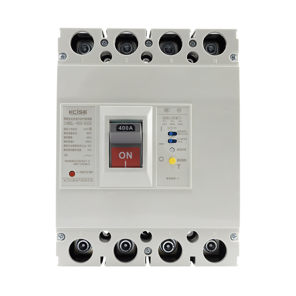


SMM2L-400L/4300 4p
KCISE
SMM2L-400L/4300
| Quantity: | |
|---|---|


A power panel has a sound you only notice when something is wrong: the sharp snap of a trip, the hollow hush after a feeder drops out, the rushed footsteps when production or building services go dark. The SMM2L series is built for that moment—when protection must be decisive, selective, and predictable.
This MCCB uses an electronic trip platform with adjustable current and time settings, allowing you to match protection to the way your load truly behaves. Instead of “guessing” with fixed thresholds, you can dial in long-delay overload and short-delay short-circuit behavior to reduce avoidable downtime while still keeping cables, busbars, and downstream equipment protected.
In the field, the experience is practical and direct: the control panel is designed to be operated easily, with visual indications for operating current status, overload, and pre-alarm—so technicians don’t have to rely only on assumptions. The enclosure is described as compact and small, helping you build cleaner layouts where space is limited.
For low-voltage distribution at AC 50Hz and 400V and below, SMM2L supports a range up to 800A with M/H breaking capacity levels. When you need to integrate control and safety, the breaker can be equipped with undervoltage release, shunt release, auxiliary and alarm contacts, motor operating mechanisms, and rotary handles—so the protection device fits your control philosophy instead of forcing a redesign.
Stable protection behavior across ambient changes
Electronic protection helps keep settings consistent, supporting reliable operation in cabinets that see temperature swings.
Adjustability that prevents “over-protection”
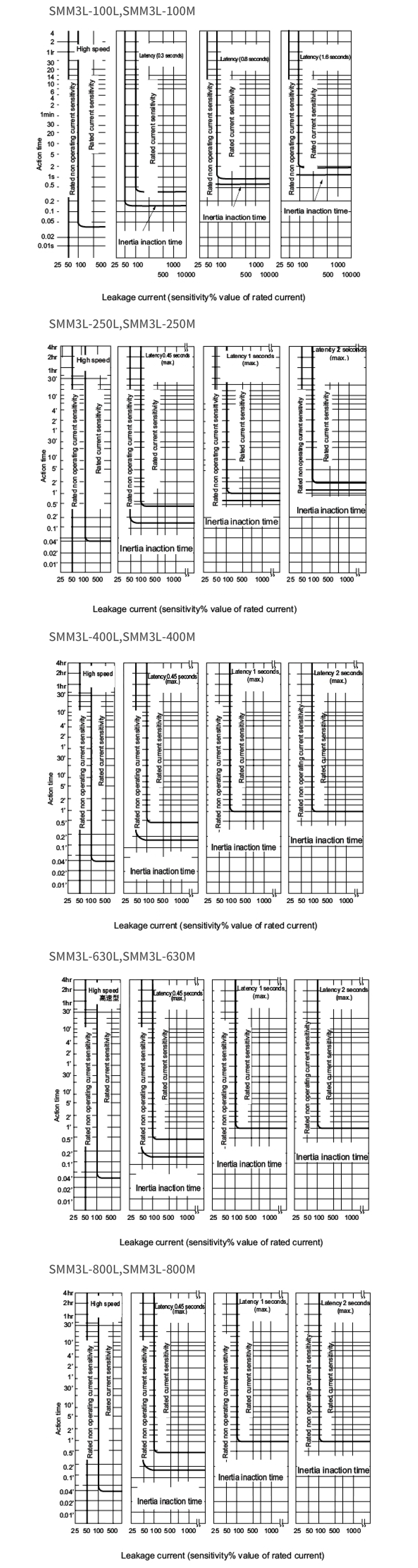
Tune rated current, overload long-delay time, short-delay pickup multiple, short-delay action time, instantaneous multiple, and pre-alarm multiple so the breaker protects without tripping on normal inrush or load variations.
High breaking capacity options (M/H)
Choose breaking capacity levels aligned with prospective fault current, improving safety margins and system continuity.
On-panel indications that speed troubleshooting
Current column indication plus overload and pre-alarm signals reduce time spent interpreting events after a trip.
Expandable with practical accessories
Add undervoltage/shunt releases for interlocking and emergency control; add contacts for signaling; add electric operator and rotary handle for operation style and accessibility.
The SMM2L electronic MCCB is intended for low-voltage distribution and provides a protection set that covers the common fault spectrum:
Overload long delay (inverse time)
Helps protect conductors and equipment from sustained overcurrent. In daily operation, this is what prevents gradual overheating that shortens insulation life.
Short-circuit short delay (inverse time + definite time options)
Short-delay capability can be used to coordinate with downstream protective devices so a local fault does not unnecessarily trip the main feeder. The benefit is fewer “whole-panel” outages and quicker restoration.
Short-circuit instantaneous
Fast interruption for severe faults, limiting thermal and mechanical stress.
Undervoltage protection
Supports controlled disconnection when voltage falls below acceptable limits, helping protect motors and sensitive loads from unstable supply conditions.
Because settings are adjustable, you can align the breaker’s response with the load profile. The goal is not “more functions,” but cleaner selectivity, fewer nuisance trips, and clearer fault separation—the things that operators notice immediately in uptime and maintenance efficiency.
In real installations, breaking capacity is not a brochure number—it’s what stands between a fault and a damaged panel. The SMM2L series provides M/H breaking capacity levels across multiple frame sizes, allowing selection based on fault-level calculations and upstream transformer capacity.
Why it matters:
Higher breaking capacity supports safer fault interruption and reduces the risk of secondary damage.
Short-delay functionality supports coordination so the closest device to the fault can isolate it, preserving availability for the rest of the system.
Proper coordination also reduces stress on upstream breakers and busbars, improving lifecycle reliability.
Typical engineering approach (practical checklist):
Estimate prospective short-circuit current at installation point
Select frame size and breaking capacity level (M/H)
Set long-delay and short-delay parameters to align with cable ampacity and downstream device curves
Verify accessory needs (UVR/shunt/contacts) for control logic and signaling
| Item | Value |
|---|---|
| Product type | Electronic molded case circuit breaker |
| Poles | 3P / 4P |
| Frequency | AC 50Hz |
| Rated working voltage (Ue) | 400V and below (table: 400V) |
| Rated insulation voltage (Ui) | 690V (description) / 800V (table) |
| Rated impulse withstand voltage (Uimp) | 8000V |
| Rated working current (max) | Up to 800A |
| Frame current (Inm) | 100 / 250 / 400 / 630 / 800A |
| Rated current (adjustable ranges) | 32A (12–32); 100A (40–100); 250A (90–250); 400A (160–400); 630A (252–630); 800A (320–800) |
| Breaking capacity level | M / H |
| Limit short-circuit breaking capacity (kA) | 100: 50/65; 250: 50/65; 400: 65/80; 630: 65/85; 800: 65/85 (M/H) |
| Operating short-circuit breaking capacity (kA) | 100: 25/50; 250: 25/50; 400: 32.5/55; 630: 65/85; 800: 65/85 (M/H) |
| Operating short-circuit withstand current | 100/250/400: 5/0.5; 630/800: 20/1 |
| Utilization category | A (100/250), B (400/630/800) |
| Arcing distance | ≤50 (small frames), ≤100 (large frames) |
| Mechanical/electrical operating performance | Power on (times): 1500/1000/1000/1000/500; No electricity (times): 8500/7000/4000/4000/2500 (by frame) |
| Indications | Operating current column; overload indication; pre-alarm indication |
| Compliance | IEC 60947 Appendix F EMC requirements |
| Protection functions | Overload long delay; short-circuit short delay (inverse + definite); short-circuit instantaneous; undervoltage protection |
| Adjustable settings | Rated current; overload long-delay time; short-delay pickup multiple; short-delay action time; instantaneous multiple; pre-alarm multiple |
Compact, cabinet-friendly form: helps keep wiring bends clean and improves accessibility when multiple feeders share a compartment.
Intuitive adjustment: the intelligent control panel is designed for straightforward setting changes, enabling commissioning teams to align protection with the load rather than accept one-size-fits-all thresholds.
Readable indication: current status, overload, and pre-alarm indications provide a quick “at-a-glance” condition check—useful during preventive inspections when you want certainty without lengthy testing.
Designed for typical duty: suitable for infrequent line switching and infrequent motor starting, matching common distribution practice where the breaker’s core job is protection and isolation.
Available accessory options help you integrate protection into control and signaling:
Undervoltage release (UVR): supports safety interlocking and controlled disconnection during undervoltage events.
Shunt release: enables remote trip from external commands (emergency stop, fire system logic, interlocks).
Auxiliary contact: provides status feedback (ON/OFF/TRIP) to indicators or controllers.
Alarm contact: supports trip-alarm signaling for faster response.
Electric operating mechanism: enables powered operation where manual access is limited.
Rotary operating handle: improves ergonomics and supports door-coupled operation on enclosures.
Main or sub-feeder protection in low-voltage distribution at 400V and below
Panelboard and switchboard protection where short-circuit breaking capacity is a key selection factor
Mixed-load feeders (heating, small motors, general loads) where adjustable long-delay helps match real operating current
Installations needing signaling and remote trip/lockout through accessories
Projects that value clear maintenance visibility via on-device indications
Built to meet IEC 60947 Appendix F EMC requirements, supporting stable operation in electrically noisy environments.
Electronic trip design supports consistent protection characteristics relative to temperature variation, helping maintain commissioning intent over time.
Parameter transparency (frame sizes, breaking capacities, impulse withstand) supports engineering review and documentation, reducing approval cycles and rework risk.
Specification-first communication: we confirm voltage, pole count, frame size, breaking capacity level, and accessory needs before finalizing the selection—reducing ordering mistakes.
Configuration support: guidance on selecting adjustable ranges and accessory combinations so the installed device matches the application, not just the catalog line.
Documentation readiness: structured product parameters and compliance statements prepared for project files and inspection checklists.
Responsive lead-time coordination: clear updates for sampling, labeling, and shipment milestones to help you keep project schedules predictable.
Q1: How do I choose between M and H breaking capacity levels?
Choose based on the calculated prospective short-circuit current at the installation point. If your fault level approaches the limit of M, select H to increase interruption margin and reduce risk during severe faults.
Q2: Can I adjust the breaker to reduce nuisance trips on motor starting or inrush?
Yes. The electronic trip design supports adjustment of long-delay overload time and short-delay parameters. Proper setting helps tolerate normal inrush while still tripping quickly on genuine faults.
Q3: Is this MCCB suitable for frequent switching duty?
It is intended for infrequent switching of lines and infrequent motor starting. If your application requires very frequent operations, share the duty cycle so the correct solution can be confirmed.
Q4: What is the benefit of pre-alarm indication?
Pre-alarm helps detect rising load current before it becomes a trip event. This allows planned corrective actions—load balancing, cable checks, or equipment inspection—without unplanned shutdown.
Q5: What accessories are available for remote control and signaling?
Common options include undervoltage release, shunt release, auxiliary contact, alarm contact, electric operating mechanism, and rotary operating handle. Share your control schematic needs to match the right combination.
Q6: The page mentions Ui 690V and the table shows 800V—what should I use in documentation?
Use the value aligned with your ordered configuration and the supplied documentation. For conservative design documentation, you may reference the lower stated value unless confirmed otherwise by the delivered product labeling/data.