


VS1-12 Handcart Type Vacuum Circuit Breaker
KCISE
VS1-12 Handcart Type Vacuum Circuit Breaker
| Rated voltage: | |
|---|---|
| Rated current: | |
| Quantity: | |


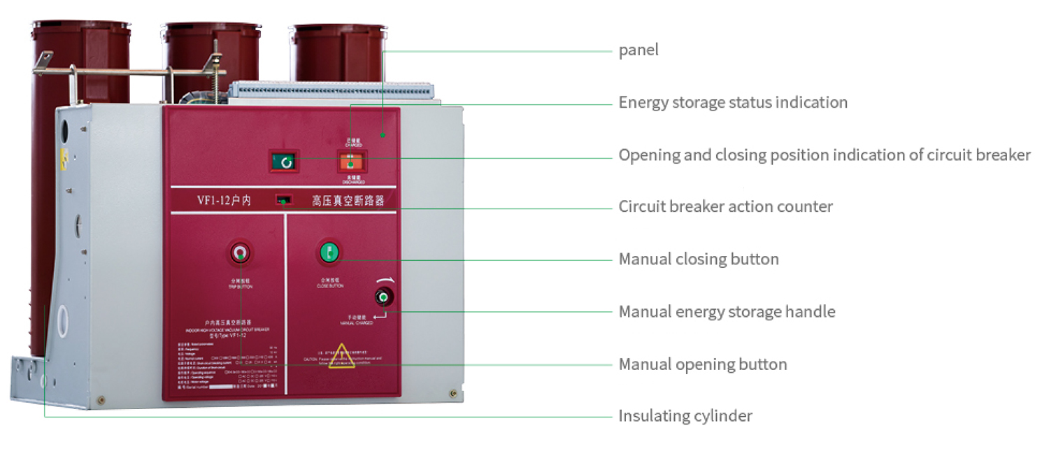
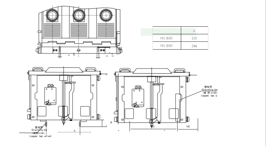
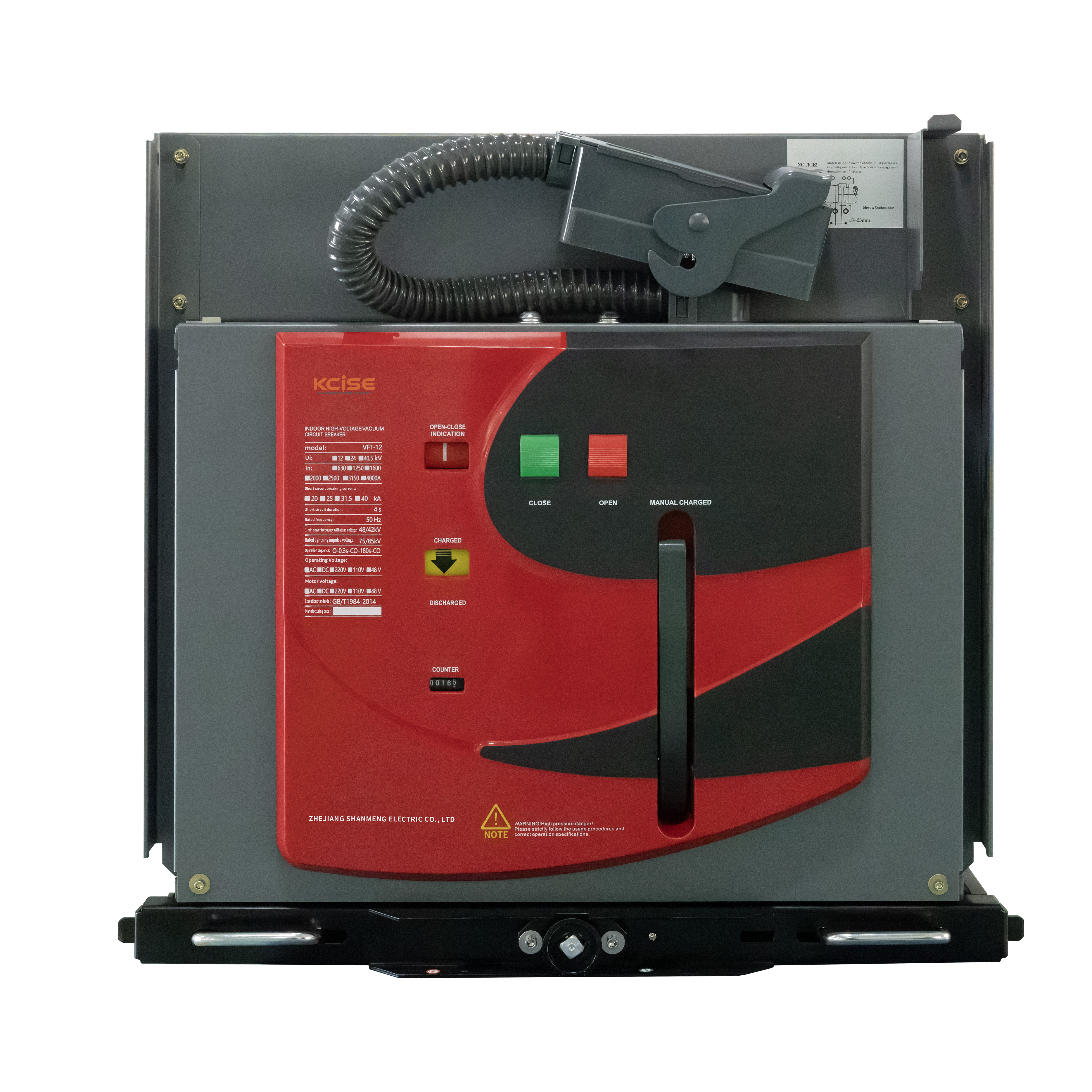
The ZN63-12(VS1) high-voltage vacuum circuit breaker is an indoor switchgear device with a rated voltage of 12 kV and a three-phase AC frequency of 50 Hz. It is an electrical protection and control device used in power systems, particularly suitable for applications that require frequent operation at rated current or repeated switching of short-circuit currents.
This circuit breaker is designed as an integrated unit combining the actuator and the breaker body. It can be used in fixed installation units, or, when equipped with a dedicated trolley mechanism, it can form a withdrawable unit. Appropriate interlocks can be added to meet the requirements of fixed cabinets such as XGN2 and GG1A. At the same time, it can be coordinated with manually operated switchgear of intermediate arrangement such as KYN28A-12 (GZS1), or with fixed switchgear such as XGN.
Normal operating and installation conditions
◎ Ambient temperature: maximum temperature: + 40 ℃ minimum temperature: - 15 ℃
◎ Ambient humidity: daily average relative humidity: ≤ 95%, monthly average relative humidity: ≤ 90%, daily average vapor pressure:
≤ 2.2 × 10⁻³mpa monthly average vapor pressure: ≤ 1.8 × 10⁻³MPa
◎ Altitude: no more than 1000M
◎ The seismic intensity shall not exceed 8 degrees
◎ The place of use shall be free of dripping water, flammable and explosive hazards, chemical corrosive gases and violent vibration.