- All
- Product Name
- Product Keyword
- Product Model
- Product Summary
- Product Description
- Multi Field Search
Please Choose Your Language

Views: 0 Author: Site Editor Publish Time: 2026-09-01 Origin: Site


Modern infrastructure relies on precise fault management and safe circuit isolation to maintain uninterrupted power. Electrical protection is a non-negotiable requirement for any facility. Specifying the wrong protection device introduces severe operational and safety risks. These range from nuisance tripping and accelerated equipment wear to catastrophic arc flash incidents and extended facility downtime. When electrical faults occur, the protection hardware must react within milliseconds to prevent fire, equipment destruction, and fatal hazards. This technical evaluation guide helps engineers, electricians, and facility managers match specific protection architectures to precise load requirements, compliance standards, and grid-based applications. Understanding the internal mechanics and application limits of an AC circuit breaker ensures your electrical distribution network remains safe, compliant, and highly reliable under all operating conditions.
Core Function: An AC circuit breaker is an electrical switch engineered to automatically interrupt current flow during overloads or short circuits, leveraging the natural zero-crossing of alternating current to extinguish electrical arcs, while also serving as a manual disconnect for maintenance.
Application Specificity: Selection depends entirely on the operational environment, spanning residential service circuits, commercial HVAC systems, institutional facilities, and heavy industrial motor protection.
Tiered Solutions: The choice between an AC Miniature Circuit Breaker, AC Moulded Case Circuit Breaker, and AC Air Circuit Breaker is dictated by voltage, current capacity, and required trip characteristics.
Safety Imperative: AC and DC breakers are not interchangeable; utilizing an AC breaker in a DC application (like solar or marine) creates severe fire and safety hazards due to the lack of specialized DC arc extinguishing mechanisms.
The baseline expectation of any circuit protection device is the reliable isolation of electrical faults. It must achieve this without degrading its own future operational integrity. You also need safe manual switching capabilities for routine maintenance and system lock-out/tag-out (LOTO) procedures. To accomplish these goals, the internal architecture relies on two distinct tripping mechanisms to handle different types of electrical anomalies.
Sustained overloads occur when a circuit draws slightly more current than its rated capacity for an extended period. Think of a commercial office where too many space heaters are plugged into a single branch circuit. To protect against this, the breaker utilizes a thermal mechanism, typically a bimetallic strip. As excess current flows through this strip, the electrical resistance generates heat. Because the strip consists of two different metals with varying coefficients of thermal expansion, it slowly bends. Once it bends far enough, it physically unlatches the trip mechanism, opening the contacts. This delayed reaction is intentional. It allows temporary, harmless current surges—like a vacuum cleaner starting up—without causing nuisance tripping.
Short circuits represent a much more severe threat. These are characterized by a massive, instantaneous spike in current, often caused by damaged wire insulation allowing phase-to-phase or phase-to-ground contact. To handle this, the breaker employs a magnetic mechanism built around a solenoid. When a short circuit occurs, the massive current surge generates a powerful magnetic field within the solenoid. This magnetic force instantly pulls a plunger or latch, forcing the breaker contacts open in a fraction of a second. This rapid response prevents wire insulation from melting and mitigates the risk of electrical fires.
The physical act of separating electrical contacts under load creates a plasma arc. The physics of alternating current provides a natural advantage here. Alternating current reverses direction constantly, dropping to zero volts 100 or 120 times a second depending on the regional 50Hz or 60Hz grid frequency. As the contacts separate, the arc is pushed upward into an arc chute—a series of parallel, insulated metal plates. The arc chute stretches, cools, and fragments the plasma. When the AC waveform hits its natural zero-crossing point, the arc loses its sustaining voltage and extinguishes completely. This natural phenomenon allows AC protection devices to clear massive faults efficiently.
| Fault Type | Detection Mechanism | Response Time | Typical Field Cause |
|---|---|---|---|
| Overload | Thermal (Bimetallic Strip) | Delayed (Seconds to Minutes) | Excessive equipment on one circuit, locked rotor on a small motor. |
| Short Circuit | Magnetic (Solenoid) | Instantaneous (Milliseconds) | Phase-to-phase fault, severed conduits, catastrophic insulation failure. |
| Ground Fault | Current Transformer / GFCI | Fast (Under 40 Milliseconds) | Moisture ingress, degraded wire insulation touching grounded metal. |
The deployment of electrical protection spans multiple sectors, each presenting unique load profiles and environmental challenges. You cannot use a one-size-fits-all approach when designing a facility's electrical distribution.
In residential, commercial, and institutional grid-based systems, these devices protect service circuits, lighting arrays, standard receptacles, and sensitive office electronics. Apartment buildings, office towers, and schools rely on these breakers to isolate localized faults. If a single workstation experiences a short circuit, the localized breaker trips, preventing the entire floor from losing power. Electricians install these in standard load centers and panelboards, ensuring that branch circuits remain isolated from one another.
Industrial and motor loads require a more robust approach. Manufacturing facilities utilize heavy machinery, large HVAC compressors, and automated production lines. These applications are characterized by high inrush currents. When a 50-horsepower industrial motor starts, it can draw six to ten times its normal operating current for several seconds. The protection hardware must tolerate this standard operational behavior without tripping, while still providing immediate protection if a genuine short circuit occurs. We utilize specialized trip curves in these environments to balance motor starting requirements with strict safety tolerances.
At the utility and infrastructure level, massive breakers serve as the primary disconnect and fault protection. Hospitals, data centers, and large-scale manufacturing plants require primary protection that can handle thousands of amps. These devices sit at the point where utility power enters the facility, often directly downstream from a pad-mounted transformer. They must be capable of interrupting catastrophic fault currents, ensuring that downstream distribution panels survive a major grid event.
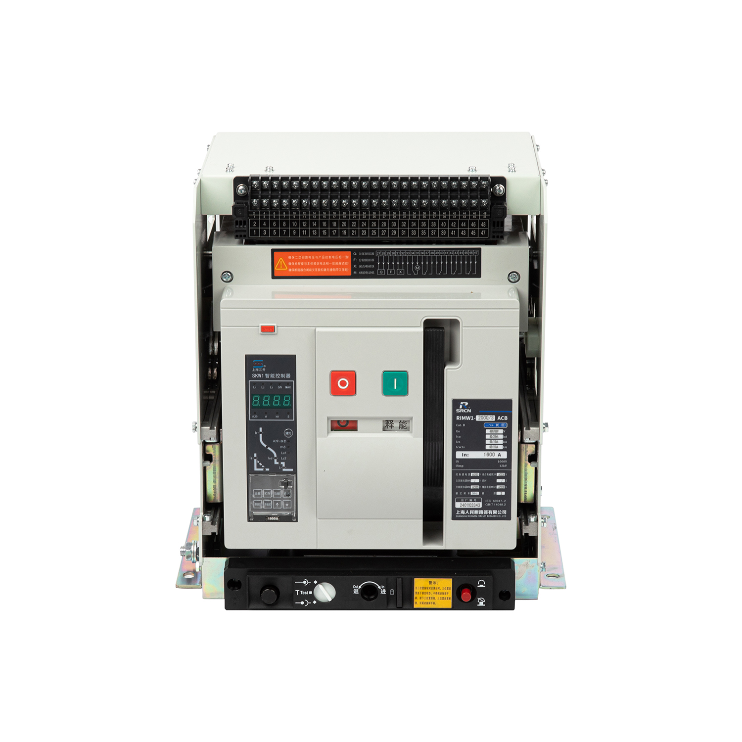
Matching the physical breaker architecture to the facility requires careful analysis of the single-line diagram. You must account for anticipated fault current, continuous load requirements, and physical space constraints within the electrical panel. The industry categorizes these solutions into three primary tiers based on their capacity, physical design, and maintenance requirements.
Low-voltage applications rely heavily on this compact architecture. You will find them deployed in final distribution boards, residential service circuits, and commercial sub-panels. They protect individual branch circuits feeding lighting and standard power outlets. Electricians typically mount these on standard 35mm DIN rails, allowing for rapid installation and replacement.
Technical specifications for an AC Miniature Circuit Breaker typically cap at a continuous current rating of 100A or 125A. They feature fixed trip settings, meaning the thermal and magnetic response thresholds are permanently set at the factory. While they are highly cost-effective and require minimal physical space, they have strict limitations. They lack the adjustability required for complex coordination schemes and do not possess the high short-circuit interrupting capacity needed for main incoming feeds. You use them strictly for final branch circuit protection.
When load demands exceed the capacity of miniature devices, facilities transition to moulded case architectures. These are heavily utilized in medium-to-high load commercial and industrial applications. They provide primary motor protection, serve as main disconnects for heavy machinery, and populate main distribution panels. They are housed in a durable, insulated composite resin enclosure that protects the internal components from dust and impact.
An AC Moulded Case Circuit Breaker offers significantly broader technical specifications. They are rated from as low as 15A up to 2500A. More importantly, they feature adjustable thermal and magnetic trip settings. Modern units utilize electronic trip units (ETUs) that allow technicians to dial in exact Long-time, Short-time, Instantaneous, and Ground-fault (LSIG) parameters. This allows engineers to fine-tune the breaker's response to match the exact thermal limits of the connected cables and equipment. They offer superior flexibility and much higher interrupting ratings, making them ideal for environments requiring precise coordination.
The highest tier of low-voltage protection is reserved for main switchgear, heavy industrial plants, and utility-scale power distribution. These massive units sit at the very top of the electrical hierarchy within a facility. They are often connected directly to the secondary side of the main utility transformer and serve as the main tie breakers in double-ended substations.
An AC Air Circuit Breaker is rated for massive loads, typically ranging from 800A up to 6300A or more. They utilize ambient air as the primary arc extinguishing medium, forcing the massive electrical arc through heavy-duty arc chutes. They are highly robust and fully maintainable. Unlike sealed MCCBs, technicians can rack an ACB out of its cassette to inspect, clean, and replace individual contacts, arc chutes, and charging motors. They are customized with advanced ETUs that provide digital monitoring, precise trip curve shaping, and network communication for SCADA systems. They require significant physical space within the switchgear and represent a major infrastructure investment.
Selecting the correct protection device requires evaluating specific technical dimensions against the desired operational outcomes. You cannot simply look at the amperage rating; you must evaluate the entire operational envelope of the device.
The continuous current rating (In) dictates the maximum current the breaker can carry continuously without tripping or suffering thermal degradation. Sizing this correctly ensures the breaker handles 100% of the continuous load, plus any required safety margins dictated by the National Electrical Code (NEC) or local regulations. For continuous loads operating for three hours or more, you typically size the breaker at 125% of the load.
The interrupting capacity, often denoted as a kA (kilo-ampere) rating, is arguably the most critical safety metric. This rating defines the absolute maximum fault current the breaker can safely clear without physically exploding or welding its contacts shut. Engineers calculate the maximum available fault current at the specific location in the network based on transformer size and cable impedance. The breaker's kA rating must exceed this calculated value. Installing a 10kA rated breaker in a panel with 65kA of available fault current is a severe code violation and a fatal safety hazard.
Trip curves define how quickly the breaker responds to overcurrents. Different loads require different response profiles to prevent nuisance tripping during normal operation.
| Trip Curve | Magnetic Trip Threshold | Target Application |
|---|---|---|
| Curve B | 3 to 5 times rated current | Fast tripping for resistive loads, long cable runs, and standard residential lighting. |
| Curve C | 5 to 10 times rated current | Moderate delay for inductive loads, small motors, and commercial fluorescent lighting. |
| Curve D / K | 10 to 14 times rated current | High inrush tolerance for transformers, heavy industrial motors, and welding equipment. |
| Curve Z | 2 to 3 times rated current | Highly sensitive electronics, instrumentation circuits, and medical imaging equipment. |
Scalability and modularity also play a vital role in modern facility design. You must evaluate whether the breaker supports field-installable accessories. Auxiliary contacts provide remote status indication to control panels. Shunt trips allow the breaker to be opened remotely by a fire alarm panel or emergency stop button. Undervoltage releases automatically trip the breaker if grid voltage drops dangerously low, protecting motors from burning out. These accessories integrate the electrical distribution system into a centralized building management system (BMS).
The fundamental nature of the power source dictates the hardware design and internal arc extinguishing technology of a circuit breaker. Alternating current and direct current behave entirely differently when a circuit is broken under load. Understanding this conceptual trade-off is vital for facility safety, especially as commercial facilities integrate more solar and battery storage systems.
The primary challenge lies in the DC arc extinguishing problem. Unlike alternating current, direct current flows continuously in one direction at a constant voltage. It does not have a zero-crossing point. When contacts separate in a DC circuit, the resulting electrical arc is incredibly stable and aggressive. It will not extinguish naturally. DC breakers require specialized internal components, such as permanent magnets or complex magnetic blowout coils, to forcefully stretch and break the arc away from the contacts and push it into the arc chutes.
The implementation risk of mixing these technologies is severe. Using an AC breaker in a high-current DC system will almost certainly result in catastrophic failure. Because the AC hardware lacks magnetic blowouts, a DC arc will sustain across the opening contacts. This sustained arcing generates immense heat, rapidly melting the internal copper components, welding the contacts together, and often rupturing the plastic enclosure. You must explicitly avoid using AC-rated breakers for Solar PV combiner boxes, automotive systems, battery energy storage systems (BESS), or marine applications. Doing so creates an immediate and severe fire hazard.
Even with the correct breaker type selected, environmental factors can compromise performance. Environmental derating is a critical engineering step. The thermal trip mechanism relies on heat to operate. If the breaker is installed in a high-temperature environment, such as a boiler room or an outdoor enclosure in a hot climate, the ambient heat will cause the bimetallic strip to bend prematurely. This leads to nuisance tripping at currents well below the rated capacity. Conversely, extreme cold can delay tripping. Altitude also affects performance; thinner air at elevations above 2000 meters reduces the cooling capacity of the breaker and lowers its dielectric strength. You must apply manufacturer derating charts during the design phase to compensate for these variables.
System coordination and selectivity ensure that a localized fault does not cause a facility-wide blackout. This involves designing the protection scheme so that the breaker closest to the fault trips first. We achieve this through the following steps:
Conduct a comprehensive short-circuit study of the entire facility.
Plot time-current curves (TCC) for all protective devices in series.
Adjust the electronic trip unit (ETU) settings on upstream moulded case and air breakers to introduce intentional delays.
Verify that the operational bands of upstream and downstream devices do not overlap on the TCC graph.
Compliance and standards dictate the legal and safety requirements for installation. You must ensure the specified breaker meets regional regulatory requirements. In North America, this typically means adherence to UL 489 standards for moulded case breakers. For international industrial applications, IEC 60947-2 is the governing standard. Furthermore, if the breaker will be used to manually turn fluorescent lighting on and off daily, it must carry a Switching Duty (SWD) or High Intensity Discharge (HID) rating. Standard breakers are not designed for high-frequency manual switching and will wear out prematurely if used as regular light switches without this specific rating.
To ensure your facility remains protected, compliant, and operationally resilient, take the following actions:
Audit your existing single-line diagrams to verify that all installed interrupting ratings exceed the maximum available fault current from the utility.
Implement a routine maintenance schedule for draw-out air breakers, including contact resistance testing and primary injection testing.
Replace any standard breakers currently used for daily lighting control with units specifically carrying a Switching Duty (SWD) rating.
Update your facility's arc flash hazard labels based on the clearing times of your newly coordinated protection devices.
A: Using an AC breaker on a DC circuit creates a severe fire hazard. DC current lacks a zero-crossing point, meaning the electrical arc generated during a fault will not extinguish naturally. The AC breaker lacks the magnetic blowouts required to break a DC arc, leading to sustained arcing, melted contacts, and potential enclosure rupture.
A: Sizing requires calculating the motor's full load amps (FLA) and accounting for inrush current during startup. You must select a breaker with a specific trip curve (like Curve D or K) that allows high temporary current spikes without tripping, while still providing immediate short-circuit protection based on local electrical codes.
A: A miniature breaker (MCB) is compact, handles low current (up to 125A), has fixed trip settings, and is used for final branch circuits. A moulded case breaker (MCCB) handles much higher loads (up to 2500A), features adjustable thermal and magnetic trip settings, and is used for main distribution and heavy industrial loads.
A: Standard breakers are not designed for frequent manual switching, as this wears out the internal mechanical linkages. However, if a breaker carries a Switching Duty (SWD) or High Intensity Discharge (HID) rating, it is explicitly tested and approved to be used as a regular switch for lighting circuits.
A: Repeated tripping without a short circuit is usually caused by a sustained overload, where the circuit is drawing slightly more current than its rating. It can also be caused by high ambient temperatures causing premature thermal tripping, a failing breaker with weakened internal springs, or harmonic currents from electronic loads.
A: A commercial breaker typically lasts 15 to 30 years under normal operating conditions. However, its lifespan is significantly reduced by frequent tripping under heavy fault currents, high ambient temperatures, corrosive environments, or lack of routine maintenance and mechanical exercising.
A: The interrupting rating (kA) indicates the maximum fault current the breaker can safely interrupt without sustaining physical damage or failing to clear the circuit. The breaker's kA rating must always be higher than the maximum available short-circuit current at its specific installation point in the electrical network.
