- All
- Product Name
- Product Keyword
- Product Model
- Product Summary
- Product Description
- Multi Field Search
Please Choose Your Language

Views: 0 Author: Site Editor Publish Time: 2026-09-04 Origin: Site


An AC circuit breaker acts as a precision-engineered line of defense against thermal degradation, catastrophic electrical faults, and equipment burnout. It is not just a basic safety switch. Improper specification creates severe operational risks. Misunderstanding breaker mechanics directly leads to nuisance tripping and premature equipment failure. Burned-out air conditioning compressors are a common result of poor sizing. Commercial and industrial environments face strict compliance violations if protection devices fail to meet load profiles. You must evaluate internal working principles before installation. Understanding thermal tripping, magnetic fault clearing, and arc extinguishing is a mandatory prerequisite. This technical baseline allows you to accurately specify pole configurations, base current values, and amperage ratings. Matching the exact breaker to specific load profiles prevents downtime and ensures facility safety.
An AC circuit breaker utilizes dual-protection mechanisms: a bimetallic strip for sustained thermal overloads and an electromagnet for instantaneous short-circuit faults.
Alternating current naturally crosses zero volts, allowing AC breakers to extinguish electrical arcs more efficiently than DC equivalents—meaning AC and DC breakers are rarely interchangeable.
The term "AC circuit breaker" carries dual significance: it governs Alternating Current circuits and serves as the primary electrical safeguard for Air Conditioning (HVAC) systems against compressor overdraws.
Selecting the correct configuration (e.g., 1P, 3P, or 4P) depends strictly on the phase requirements of the load and the necessity of neutral wire isolation.
Proper specification requires aligning the breaker’s trip curve (B, C, or D) with the inrush current characteristics of the connected equipment to prevent operational downtime.
The thermal tripping mechanism relies on the predictable physics of a bimetallic strip. This component consists of two distinct metals, typically brass and invar, welded together. Each metal possesses a different coefficient of thermal expansion. When electrical current flows through the breaker terminals, it generates heat across this strip. Normal operating currents produce minimal heat. The strip remains straight and the circuit stays closed.
Prolonged current draw above the rated base current changes this dynamic. The excessive current generates high heat, causing the bimetallic strip to bend. The metal with the higher expansion rate elongates faster, forcing the entire assembly to curve. As it bends, it mechanically triggers the internal trip latch. This action separates the contacts and breaks the circuit. The thermal trip features an inverse time characteristic. A minor 10% overload might take twenty minutes to trip the breaker. A massive 50% overload will bend the strip rapidly, tripping the device in seconds. This delay is intentional. It allows motors and compressors to draw temporary starting currents without dropping the circuit.
Short circuits require immediate, violent intervention. Thermal tripping is far too slow to handle massive fault currents. The magnetic tripping mechanism takes over during these events. The core component is an electromagnetic coil, or solenoid, wired in series with the load. During normal operation, the magnetic field generated by the load current remains weak. It exerts no pull on the internal trip armature.
A dead short circuit changes the magnetic field instantly. A massive fault current surges through the coil, magnifying the magnetic field exponentially. This intensified field generates immense mechanical force. It pulls an internal iron plunger with violent speed. The plunger strikes the trip bar, breaking the circuit in mere milliseconds. This rapid response limits the let-through energy. It prevents wire insulation from melting, stops copper conductors from vaporizing, and eliminates the risk of electrical fires.
Separating live electrical contacts under a heavy load creates an electrical arc. This arc is a bridge of conductive plasma burning at thousands of degrees Celsius. The breaker must extinguish this arc immediately to survive the fault. It uses an arc chute, also known as an arc divider, to accomplish this task. The arc chute consists of parallel, copper-plated steel plates arranged in a grid. Magnetic forces generated by the fault push the arc away from the contacts and directly into this grid.
The grid stretches, cools, and splits the massive arc into smaller, manageable segments. Alternating current provides a distinct physical advantage during this process. The zero-crossing phenomenon is inherent to AC power. The voltage drops to absolute zero 100 or 120 times per second, depending on the 50Hz or 60Hz grid frequency. The breaker leverages this microsecond window of zero voltage. It cools the segmented arc just enough so the plasma loses its conductivity. The arc cannot reignite when the voltage rises again on the next cycle.
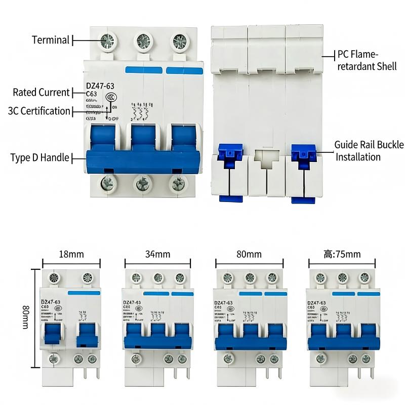
A 1-pole (1P) breaker represents the standard configuration in residential and light commercial electrical panels. It protects a single live wire. The neutral wire typically connects directly to a common busbar and remains unswitched. The operational scope of a 1P breaker covers standard 120V or 230V single-phase circuits. It provides straightforward thermal and magnetic protection for individual branch circuits.
Electricians frequently deploy a 1P 32A AC Circuit Breaker for heavy-duty residential appliances. It easily handles the continuous load of residential air conditioning units, electric water heaters, and induction cooktops. Light commercial lighting circuits and single-phase server racks also rely heavily on this specific amperage. When installing a 1P breaker, you must ensure the wire gauge matches the 32A rating. Using undersized wire with a 32A breaker creates a severe fire hazard, as the wire will melt before the breaker trips.
Follow these steps when deploying single-pole breakers:
Verify the total continuous load does not exceed 80% of the breaker's rating.
Confirm the wire gauge is rated for at least 32 amps (typically 4mm² or 10 AWG minimum).
Strip the wire to the manufacturer's specified length to ensure full contact inside the terminal.
Seat the breaker firmly onto the DIN rail, ensuring the mounting clip engages fully.
Tighten the terminal screw to the exact torque specification listed on the breaker housing.
Industrial and heavy commercial facilities operate almost exclusively on three-phase power. A 3-pole (3P) breaker protects all three live wires simultaneously. The critical feature of a 3P breaker is its internal common trip linkage. If a fault occurs on phase A, the mechanical linkage ensures phase B and phase C disconnect at the exact same millisecond. This prevents single-phasing. Single-phasing is a dangerous electrical condition that rapidly overheats and destroys three-phase induction motors.
The scalability of a 3P 10A–63A AC Circuit Breaker makes it incredibly versatile across industrial sites. You can protect small commercial HVAC fans with the lower 10A models. The higher 63A models easily handle heavy machinery, conveyor belts, and large industrial pumps. Selecting the specific amperage requires careful evaluation of the motor's continuous load and its starting torque. You must ensure the breaker can handle the initial inrush current without nuisance tripping while still providing tight overload protection for the motor windings.
| Amperage Rating | Typical Three-Phase Application | Common Wire Gauge (Copper) |
|---|---|---|
| 10A - 16A | Small exhaust fans, control circuits, light machine tools | 1.5mm² - 2.5mm² |
| 20A - 32A | Commercial HVAC units, medium induction motors, commercial ovens | 4.0mm² - 6.0mm² |
| 40A - 63A | Heavy industrial pumps, large compressors, main sub-panel feeds | 10.0mm² - 16.0mm² |
A 4-pole (4P) breaker differentiates itself by including a switched neutral pole alongside the three live phases. While a standard 3P breaker leaves the neutral wire permanently connected to the busbar, a 4P breaker severs it entirely during a trip. This provides complete electrical isolation from the grid. The neutral pole usually features early-make and late-break contacts. This design ensures the neutral connects first and disconnects last, maintaining stable voltage across the phases during switching operations.
Strict compliance and safety scenarios often require a 4P 63A AC Circuit Breaker. Backup generator changeover panels mandate 4P breakers to prevent dangerous backfeeding through the neutral line. If the neutral remains connected, ground fault relays on the generator can malfunction. Critical IT infrastructure and data centers use 4P breakers to guarantee total isolation during maintenance. Furthermore, environments with high harmonic distortion pose severe risks. Harmonics generated by LED lighting and variable frequency drives can cause massive currents to accumulate on the neutral wire. A switched neutral pole becomes a mandatory safety requirement to prevent neutral wire fires.
The terminology carries a dual intent in the electrical industry. An AC circuit breaker governs alternating current, but it also specifically protects an air conditioning (AC) unit. Air conditioners present unique electrical challenges. They contain large compressors that require massive surges of power to start. This is known as Locked Rotor Amps (LRA). The breaker must accommodate this massive surge while remaining sensitive enough to detect a genuine fault based on the Full Load Amps (FLA).
The breaker constantly monitors the AC unit's compressor. If the compressor experiences a hard start or mechanical failure, it pulls significantly more power than the breaker's base current value. Dirty condenser coils, failing capacitors, or low refrigerant levels can also cause this overdraw. When the current exceeds safe limits, the breaker's thermal mechanism heats up and automatically interrupts the flow. This rapid intervention prevents electrical fires in the wall wiring and stops permanent damage to the expensive HVAC equipment.
You cannot safely interrupt a direct current (DC) fault using an alternating current breaker. The underlying physics of the two power types are completely different. AC power naturally crosses zero volts multiple times per second. DC power provides a continuous, unyielding flow of voltage. It never drops to zero. This makes extinguishing a DC electrical arc significantly more difficult.
If you install an AC breaker in a DC circuit, the arc will sustain much longer during a fault. The lack of a zero-crossing means the plasma arc continues to burn across the separating contacts. This prolonged arcing will rapidly melt the breaker's internal components. It poses a severe fire risk and practically guarantees catastrophic failure. DC breakers require specialized magnetic blowout mechanisms. These powerful magnets actively force the stubborn DC arc into the arc chute. Standard AC magnetic trips lack this directional blowout force, rendering them useless and dangerous in DC applications like solar photovoltaic systems or battery storage banks.
| Feature | AC Circuit Breaker | DC Circuit Breaker |
|---|---|---|
| Voltage Zero-Crossing | Yes (100/120 times per second) | No (Continuous voltage) |
| Arc Extinguishing Method | Relies on zero-crossing and standard arc chute | Requires magnetic blowouts to force arc into chute |
| Contact Separation Speed | Standard speed | Requires faster separation to break continuous arc |
| Application Interchangeability | Cannot be used on DC circuits | Sometimes rated for AC, but usually DC specific |
Selecting the right form factor is the first step in electrical design. Miniature Circuit Breakers (MCBs) handle sub-100A applications. They are compact, standardized devices designed for DIN rail mounting. You will find them in residential load centers, light commercial distribution boards, and machine control panels. They offer fixed trip settings and reliable protection for standard branch circuits.
Molded Case Circuit Breakers (MCCBs) serve higher current demands. They handle loads ranging from 100A up to 2500A or more. MCCBs feature robust, heavy-duty plastic enclosures designed to withstand massive fault currents. Unlike MCBs, they often provide adjustable trip settings. You can fine-tune the thermal and magnetic response dials on the front of the breaker to match complex industrial loads perfectly. Use MCCBs for main service entrances, large motor protection, and heavy industrial feeders.
Sizing a breaker requires precise mathematical calculation. You cannot simply guess the required amperage based on wire size alone. Use the standard sizing formula for continuous loads: (Continuous Load x 125%) + Non-Continuous Load. A continuous load operates for three hours or more. Multiplying by 125% provides a necessary safety buffer. This prevents the breaker from running at maximum capacity constantly, which causes premature thermal degradation of the bimetallic strip.
Follow this process to size a breaker correctly:
Identify all devices connected to the circuit and determine their running wattage.
Divide the total wattage by the system voltage to find the total amperage.
Classify the load as continuous (runs >3 hours) or non-continuous.
Apply the 125% multiplier to the continuous portion of the load.
Select the next standard breaker size up from your calculated total.
You must also account for ambient temperature derating. High-heat environments alter the thermal tripping threshold. If you install a breaker in an outdoor enclosure under direct sunlight or inside a hot boiler room, the ambient heat pre-warps the bimetallic strip. It will trip at a lower current than its rating. You must consult the manufacturer's derating charts. A 32A breaker operating in a 50°C environment might only hold 28A before tripping. You may need to upsize the breaker slightly to prevent frustrating nuisance tripping in hot environments.
The trip curve defines how the breaker responds to short-term current surges. Equipment like motors, transformers, and large LED lighting arrays draw massive inrush currents when first powered on. If the trip curve is too sensitive, the breaker will trip every time you start the machine. You must match the curve to the load profile to ensure reliable operation.
| Trip Curve Type | Magnetic Trip Threshold | Typical Load Applications | Common Environments |
|---|---|---|---|
| Curve B | 3 to 5 times rated current | Resistive loads, standard lighting, resistive heaters, long cable runs | Residential wiring, light commercial offices, domestic appliances |
| Curve C | 5 to 10 times rated current | Inductive loads, commercial motors, AC compressors, fluorescent lighting | HVAC systems, manufacturing facilities, server rooms, commercial kitchens |
| Curve D | 10 to 20 times rated current | High inrush loads, transformers, welding equipment, x-ray machines | Heavy industrial plants, medical imaging suites, large motor starting |
Selecting a Curve B breaker for an air conditioner guarantees nuisance tripping. The compressor's starting surge easily exceeds 5 times the rated current. Always specify Curve C for standard inductive loads and HVAC equipment. Reserve Curve D strictly for highly specialized industrial machinery with violent starting surges. Using a Curve D breaker on a standard residential circuit is dangerous, as it will not trip fast enough during a moderate short circuit.
Electrical safety relies heavily on international testing standards. You must evaluate breakers through mandatory compliance lenses before installation. IEC 60898-1 governs breakers designed for residential and light commercial sites. These devices are designed to be operated by uninstructed personnel. They have fixed trip settings and lower fault tolerances. IEC 60947-2 applies strictly to industrial applications. Breakers meeting this standard offer higher performance metrics, adjustable settings, and are intended for operation by skilled electricians.
You must verify the Short-Circuit Breaking Capacity, commonly known as the kA rating. This number indicates the maximum fault current the breaker can safely interrupt without exploding. A residential panel might only require a 6kA rating. An industrial facility located near a main utility substation might possess a prospective fault current of 25kA or higher. Installing a 6kA breaker in a 25kA environment creates a deadly shrapnel hazard. The breaker will physically shatter during a dead short, failing to clear the fault and causing a massive arc flash.
Nuisance tripping disrupts operations and frustrates facility managers. Identifying the root cause requires systematic troubleshooting rather than simply resetting the breaker. Mismatched trip curves are the most common culprit. Upgrading a warehouse lighting circuit to high-bay LED fixtures can alter the inrush profile, causing unexpected trips on a Curve B breaker. Harmonic distortion from variable frequency drives (VFDs) can confuse the breaker's thermal mechanism, causing it to heat up prematurely.
Loose terminal connections generate localized heat. This heat transfers directly into the breaker casing, simulating an overload condition right at the bimetallic strip. HVAC-specific issues also cause frequent tripping. A dirty air filter forces the blower motor to work harder, overdrawing current. Low refrigerant causes the compressor to overheat and pull excess amperage. Implement strict mitigation steps to solve these issues. Conduct comprehensive power quality audits using true RMS meters. Perform mechanical inspections on all HVAC units before the cooling season begins. Ensure all terminal screws are tightened to the correct specifications.
Proper installation dictates the lifespan of the breaker. You must use calibrated torque screwdrivers during installation. Over-tightening the terminal screws strips the threads and damages the copper wire strands. Under-tightening creates high-resistance connections. High resistance generates extreme heat, which eventually melts the breaker casing and causes thermal trips well below the rated amperage.
Implement a realistic lifecycle maintenance schedule to ensure ongoing protection:
Perform visual inspections monthly to check for casing discoloration, melted plastic, or strange ozone odors.
Conduct thermal imaging scans annually on all distribution boards. A FLIR camera easily spots hot terminals before they cause a catastrophic failure.
Execute mechanical trip testing during scheduled facility shutdowns. Manually toggling the breaker exercises the internal springs and ensures the mechanical latch remains free of dust and corrosion.
Check terminal torque values annually, as thermal cycling causes copper wires to expand and contract, loosening the connections over time.
Audit your current single-line electrical diagrams to ensure all breaker ratings and trip curves match the connected loads.
Calculate exact continuous load requirements and inrush currents for all heavy equipment before purchasing new protection devices.
Consult a certified electrical distributor to procure the correct IEC or UL-rated breakers for your specific environment and prospective fault current.
Schedule a comprehensive thermal imaging inspection of your main distribution panels to identify loose connections and overloaded phases.
Implement a mandatory torque-specification policy for all new breaker installations to eliminate high-resistance terminal failures.
A: It automatically interrupts electrical current during irregularities like overloads and short circuits. This rapid disconnection protects wire insulation from melting and prevents connected equipment from catching fire or sustaining permanent damage.
A: The AC unit is pulling more power than the breaker's rated capacity. This often happens due to a failing compressor, dirty condenser coils, or a grounded motor wire. It requires an immediate mechanical inspection to prevent electrical hazards.
A: No. AC breakers rely on the natural zero-crossing of alternating current to extinguish arcs. DC power lacks this zero-crossing, meaning an AC breaker cannot safely extinguish a DC arc. Using one creates a severe fire risk.
A: A 3P breaker protects three live phases and disconnects them simultaneously during a fault. A 4P breaker protects those three phases but also switches the neutral line, providing complete electrical isolation required for backup generators and critical systems.
A: Immediate tripping indicates a hard short circuit or a completely grounded phase. The breaker is doing its job by preventing catastrophic failure. Do not repeatedly reset it; you must perform diagnostic testing to locate the dead short.
A: Base your choice on the expected inrush current. Use Curve B for resistive loads like heaters. Select Curve C for inductive loads like AC compressors and standard motors. Choose Curve D for high-inrush equipment like transformers and heavy machinery.
