- All
- Product Name
- Product Keyword
- Product Model
- Product Summary
- Product Description
- Multi Field Search
Please Choose Your Language

Views: 0 Author: Site Editor Publish Time: 2026-08-26 Origin: Site


Electrical systems demand precise circuit protection to maintain safety and operational continuity. Engineers face a constant challenge on site. You must balance rapid fault isolation with the operational necessity of tolerating transient inrush currents without triggering nuisance tripping. Misapplying tripping curves directly results in severe consequences. Installing a Type B breaker on an inductive motor load guarantees premature tripping and operational downtime. Conversely, specifying a Type D breaker for a standard lighting circuit risks delayed tripping during a fault, creating severe fire and equipment hazards.
Solving this engineering challenge requires a methodical approach. You must evaluate base load currents, calculate inrush multipliers, and determine exact pole configurations. Specifying the correct miniature circuit breaker ensures robust protection for residential, commercial, and industrial applications. This technical guide explores the differences between Type B, C, and D tripping curves to help you execute precise electrical installations.
Type B is for resistive loads: Trips at 3 to 5 times full load current; ideal for standard lighting and domestic circuits with minimal inrush.
Type C is for moderate inductive loads: Trips at 5 to 10 times full load current; the standard for commercial lighting, small motors, and general industrial applications.
Type D is strictly for high-inrush applications: Trips at 10 to 20 times full load current; reserved for heavy industrial motors, transformers, and X-ray machines.
Pole configuration dictates system compatibility: Selection between 1P, 3P, and 4P configurations must align with phase requirements and neutral isolation standards.
Sizing precedes curve selection: The breaker's rated current must always exceed the continuous load current before evaluating the required B, C, or D tripping curve.
Modern electrical infrastructure relies on dual-functionality circuit protection. A standard breaker integrates two distinct mechanical systems to safeguard wiring and connected devices. You cannot rely on a single mechanism to handle both slow-building overloads and instantaneous short circuits. The internal architecture of these devices reflects the reality of field conditions, where faults manifest in entirely different ways.
The first mechanism provides thermal protection. A calibrated bimetallic strip sits inside the breaker housing. When current flows through the circuit, it generates heat. During a sustained overload—like plugging too many space heaters into a single ring main—the bimetallic strip heats up and physically bends. This gradual deformation eventually triggers the mechanical trip latch. It effectively prevents long-term overheating that degrades cable insulation and starts electrical fires. The thermal response is intentionally slow. It ignores brief surges and only reacts to continuous overcurrent conditions.
The second mechanism delivers magnetic protection. A precision solenoid coil handles this function. It responds instantly to extreme current spikes caused by dead short circuits, such as a live wire touching an exposed copper pipe. When a massive fault occurs, the current surges through the coil, generating a powerful magnetic field. This field pulls an internal armature, striking the trip latch immediately. The contacts separate in milliseconds, extinguishing the internal arc via the arc chute and isolating the fault.
While all standard breakers perform these two functions, their field application varies drastically. The differentiation lies entirely in the magnetic trip threshold. This threshold defines the tripping curve. It dictates exactly how the breaker responds to transient currents and normal equipment startup surges. Selecting the right curve prevents nuisance tripping while maintaining strict safety margins for the installed cable.
| Protection Type | Internal Mechanism | Response Time | Target Fault Condition |
|---|---|---|---|
| Thermal Overload | Bimetallic Strip | Seconds to Minutes | Sustained overcurrent (e.g., overloaded sockets) |
| Magnetic Short-Circuit | Solenoid Coil | Milliseconds | Dead short circuits (e.g., live to earth faults) |
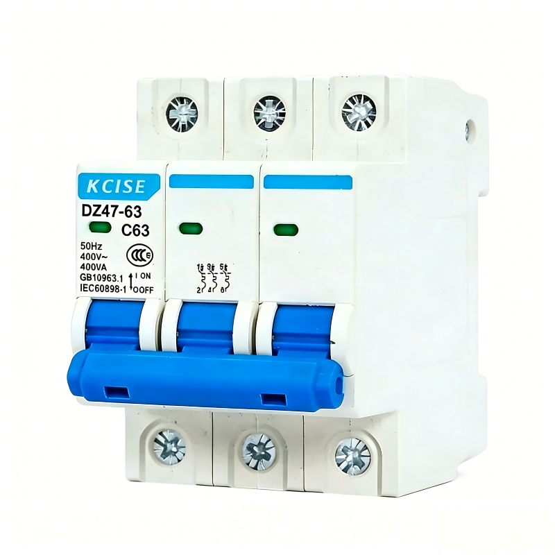
Type B curves offer highly sensitive magnetic protection. The technical threshold for a Type B device is set between 3 and 5 times the rated current. If you install a 10A Type B breaker, the magnetic trip actuates instantly when the current hits 30A to 50A. This tight tolerance makes it highly responsive to minor fault currents, ensuring rapid disconnection even on circuits with slightly higher earth fault loop impedance.
Engineers specify Type B primarily for domestic and light commercial environments. Target applications include standard household outlets, resistive space heaters, and traditional lighting circuits. These loads draw a steady, predictable current upon startup. They do not generate significant transient spikes. When you flip a switch for a resistive load, the current immediately settles at its operational baseline.
However, Type B has strict limitations on site. It fails frequently in commercial settings equipped with switching power supplies or small motors. Starting a commercial vacuum cleaner or powering up a bank of office computer monitors creates a brief inrush current. This surge easily exceeds the 3x to 5x threshold. The result is inevitable nuisance tripping. Facility managers often misdiagnose this as a faulty breaker, when the reality is simply a misapplied tripping curve.
Type C curves provide a robust middle ground for modern electrical loads. The magnetic trip setting operates between 5 and 10 times the rated current. A 10A Type C breaker requires a transient spike of 50A to 100A to trigger the instantaneous magnetic release. This broader threshold accommodates normal operational surges without compromising the overall safety of the distribution network.
This curve serves as the default standard for commercial and general industrial applications. Target use cases include fluorescent and LED lighting circuits, small electric motors, ventilation fans, and IT server racks. LED drivers, in particular, are notorious for pulling massive inrush currents for a fraction of a millisecond as their internal capacitors charge. A Type C breaker rides through this transient spike seamlessly.
The primary trade-off involves fault clearance speed and cable sizing. Type C offers excellent balanced tolerance for transients. However, it requires a higher fault current to trip instantly compared to Type B. You must ensure the circuit wiring can safely carry this higher fault current for the brief duration before the breaker actuates. If you install a Type C breaker on a long cable run with high loop impedance, a short circuit might not generate enough current to hit the 5x to 10x multiplier. In that scenario, the breaker relies on the slower thermal strip, potentially allowing the cable to overheat.
Type D curves handle extreme transient currents without interrupting power. The magnetic trip setting is exceptionally high, actuating at 10 to 20 times the rated current. A 10A Type D breaker ignores surges up to 100A or even 200A. This massive tolerance is necessary for specific heavy-duty equipment that behaves almost like a short circuit during its initial startup phase.
You will find Type D breakers exclusively in demanding industrial environments. Target applications include large step-down transformers, heavy winding motors, industrial welding equipment, and large-scale uninterruptible power supplies. When a heavy industrial motor starts across the line, it requires massive amperage to overcome mechanical inertia and establish its magnetic field. A Type D breaker allows this process to occur without tripping the board.
Implementation requires strict caution and rigorous testing. You should never use Type D for general-purpose circuits or residential panels. The high trip threshold allows sustained fault currents to flow through the system. If a short circuit occurs on standard wiring protected by a Type D breaker, the cable may melt or catch fire before the device recognizes the fault. You must verify with a multifunction tester that the earth fault loop impedance (Zs) is exceptionally low. The circuit must be capable of generating a fault current high enough to trip the device safely within the required disconnection time.
While B, C, and D curves cover roughly 95% of standard electrical applications, some environments demand specialized protection. Manufacturers produce highly specific tripping curves to address unique operational vulnerabilities. Understanding these niche options helps you protect highly sensitive or specialized equipment on complex industrial sites.
Type A breakers offer extreme sensitivity. They trip at merely 2 to 3 times the rated current. Engineers utilize them primarily for protecting delicate semiconductor devices, programmable logic controllers (PLCs), and highly sensitive measuring instruments. These circuits cannot tolerate even minor overcurrents without sustaining permanent hardware damage. The tight magnetic threshold ensures immediate isolation at the first sign of a fault.
Types K and Z fulfill distinct roles in advanced industrial settings. Type K is optimized specifically for motor loads. It provides a highly tailored thermal trip curve to prevent motor winding degradation while allowing high magnetic inrush. Type Z is designed for ultra-sensitive electronics. It requires rapid short-circuit clearance, tripping at 2 to 3 times the rated current, but features a different thermal profile than Type A. These specialty curves ensure precise protection where standard options fall short.
Single-pole configurations provide fundamental single-phase protection. They monitor and disconnect only the live wire during a fault condition. The neutral wire remains continuously connected to the system block inside the distribution board. This is the most common configuration you will encounter in standard wiring.
You will deploy a 1P AC Miniature Circuit Breaker primarily in standard 230V or 240V residential and light commercial circuits. These devices offer significant space-saving benefits in crowded distribution boards. They are the optimal choice where neutral switching is not legally mandated or technically required by the local earthing system. Using single-pole breakers allows for high-density panel layouts, maximizing the number of outgoing ways in a compact enclosure.
Three-pole configurations deliver synchronized three-phase protection. They monitor L1, L2, and L3 simultaneously. If a fault occurs on any single phase, the internal mechanical linkage trips all three poles instantly. This configuration does not include a neutral disconnect, making it suitable for balanced three-phase loads.
A 3P AC Miniature Circuit Breaker is essential for industrial motors, three-phase pumps, and heavy manufacturing machinery. The common trip mechanism is critical here. It prevents single-phasing, a dangerous condition where a three-phase motor loses one phase but continues to run on the remaining two. Single-phasing causes the motor to draw excessive current on the active phases, leading to rapid overheating, insulation breakdown, and catastrophic motor failure.
Four-pole configurations provide comprehensive three-phase plus neutral protection. They monitor and isolate L1, L2, L3, and the neutral conductor simultaneously. This ensures complete electrical isolation of the connected circuit, severing all active conductors from the supply.
Specifying a 4P AC Miniature Circuit Breaker is critical for systems requiring absolute isolation for safe maintenance. They are mandatory in installations with high harmonic currents in the neutral wire, which can cause the neutral to carry significant current and pose a shock hazard. Furthermore, specific earthing arrangements, such as TT systems, strictly demand complete neutral disconnection during a fault to prevent dangerous voltage potentials from traveling back through the neutral conductor.
Accurate specification requires evaluating multiple technical dimensions simultaneously. You cannot select a breaker based on the tripping curve alone. A systematic approach ensures the device performs reliably under both normal and fault conditions. Field engineers follow a strict sequence of calculations before ordering components for a distribution board.
First, establish the base current sizing. The breaker's rated current (In) must always be higher than the continuous load current of the circuit, but lower than the current-carrying capacity of the cable (Iz). Standard sizing ranges widely, typically from 6A up to 63A or 125A. You must also account for ambient temperature derating. Breakers installed in hot environments or tightly packed enclosures may trip below their rated current due to ambient heat affecting the bimetallic strip. If you install multiple breakers side-by-side in a poorly ventilated panel, you must apply a grouping factor to derate their effective capacity.
Next, perform a detailed load characteristics and inrush current analysis. Calculate the expected inrush multiplier of the connected equipment. Review motor nameplates or manufacturer datasheets to find the Locked Rotor Amps (LRA). Map this multiplier directly to the B, C, or D curve thresholds to prevent nuisance tripping during standard operations. If a motor pulls 60A on startup and runs at 10A, a 10A Type B breaker will trip immediately. A 10A Type C might hold, but a 10A Type D provides the safest margin for reliable operation.
You must also verify the short-circuit breaking capacity. This rating, expressed in kiloamps (kA), defines the maximum fault current the breaker can safely interrupt without destroying itself or welding its contacts shut. Residential applications typically require 6kA ratings. Commercial and industrial panels often demand 10kA, 15kA, or higher, depending on the proximity to the supply transformer. Remember that the tripping curve (B, C, D) does not dictate this breaking capacity. You can purchase a Type C breaker in both 6kA and 10kA variants.
Finally, ensure strict compliance with international standards. Reference relevant IEC or EN standards. For standard AC applications, IEC 60898-1 provides the regulatory safety benchmarks for low-voltage circuit protection operated by uninstructed persons. For industrial applications where skilled personnel operate the equipment, IEC 60947-2 applies. Compliance guarantees the device has undergone rigorous independent testing for mechanical endurance and short-circuit performance.
Calculate the total continuous design current (Ib) of the circuit.
Select a cable size with a current-carrying capacity (Iz) greater than the design current.
Choose a breaker rating (In) that sits between the design current and the cable capacity (Ib ≤ In ≤ Iz).
Determine the inrush characteristics of the load to select the correct B, C, or D curve.
Verify the prospective fault current (PFC) at the board to select the correct kA breaking capacity.
Specifying circuit protection involves navigating significant operational risks. The most common error on site is misjudging the balance between nuisance tripping and delayed protection. Over-specifying a breaker creates severe hazards. If you use a Type D curve where a Type C is adequate, you compromise cable protection. The wiring may overheat during a moderate short circuit because the breaker waits for a massive current spike before tripping. The cable essentially becomes the fuse, melting its insulation and potentially igniting surrounding building materials.
Conversely, under-specifying causes continuous operational disruption. Installing a Type B breaker for a commercial refrigeration unit guarantees the breaker will trip every time the compressor starts. This leads to spoiled inventory, frustrated facility managers, and expensive emergency call-outs for electrical contractors. The contractor often has to return to site, isolate the board, and swap the breaker for a Type C, wasting time and labor.
Another major risk involves cascading failures and poor selectivity. You must coordinate the sub-circuit breaker with upstream protection devices, such as molded case circuit breakers (MCCBs) or main incoming fuses. Proper discrimination ensures that only the breaker closest to the fault trips. If a minor short circuit on a lighting branch trips the main facility breaker, your selectivity has failed, causing unnecessary widespread blackouts across the entire building.
To mitigate these risks, execute comprehensive load profiling before installation. Measure the actual startup currents using a calibrated power quality analyzer. Furthermore, conduct mandatory loop impedance testing (Zs) at the furthest point of the circuit. This verifies that the circuit can actually generate enough fault current to trigger the selected magnetic trip threshold instantly. If the Zs reading is too high, you must either increase the cable cross-sectional area to lower the resistance or select a more sensitive tripping curve.
Measure actual startup currents using a calibrated power quality analyzer before specifying breaker curves for new industrial machinery.
Verify fault loop impedance (Zs) at the furthest point of the circuit to guarantee the fault current will trigger the instantaneous magnetic trip.
Audit existing distribution boards to ensure upstream MCCBs provide proper discrimination and selectivity with downstream sub-circuits.
Update single-line diagrams to reflect exact pole configurations and neutral isolation requirements for maintenance safety protocols.
A: Yes, replacing it will likely stop the nuisance tripping caused by moderate inrush currents. However, you must first verify that the existing cable sizing and the circuit's fault loop impedance can safely handle the higher fault current required to trip a Type C breaker. Failing to check this violates safety regulations and creates fire hazards.
A: Miniature circuit breakers are designed for lower current sub-circuits, typically rated up to 63A or 125A, with fixed trip settings. Molded case circuit breakers are larger, robust devices used for higher current mains and feeders, often featuring adjustable thermal and magnetic trip settings for precise system coordination.
A: You need a four-pole breaker when your system requires complete electrical isolation, including the neutral wire. This is mandatory for safe maintenance in certain industrial setups, in installations with severe neutral harmonics, or within specific earthing arrangements like TT systems that demand full neutral disconnection during faults.
A: No, the thermal overload protection remains generally identical across Type B, C, and D breakers. They all use a similar bimetallic strip mechanism to protect against sustained, slow-building overcurrents. The classification letters refer exclusively to their different magnetic short-circuit response thresholds.
A: You should strongly avoid using Type D breakers in residential settings. Standard domestic wiring is not designed to withstand the massive 10x to 20x fault currents that a Type D breaker allows before tripping. This delayed response can easily melt residential cables and start electrical fires.
A: You can determine the inrush current by checking the manufacturer's technical datasheets or reading the motor nameplate, which often lists the locked rotor amp rating. For precise real-world data, connect a professional power quality analyzer to the circuit during the equipment's startup phase.
A: These are highly specialized breakers. Type A protects ultra-sensitive semiconductors and measuring instruments. Type K provides optimized thermal and magnetic profiles specifically for industrial motor loads. Type Z is designed to clear short circuits extremely rapidly to protect delicate electronics that standard B, C, or D curves cannot safeguard.
